
Wireless local area network (Wireless Local Area Network, WLAN) is a network system that uses wireless communication technology to interconnect computer devices to form a mutual communication and achieve resource sharing. The characteristic of wireless local area network is that it does not use communication cables. The wireless transmission media can enable communication terminals to access the communication network flexibly, conveniently and mobilely within a certain range. Therefore, as an extension of the wired local area network, the wireless local area network has broad development prospects. However, some problems also occurred during the construction and maintenance of the WLAN project:
1) When the number of online users is large and the data traffic on the network is large, the quality of the entire network will deteriorate sharply. The performance is as follows: the data packet on the link is seriously dropped; the network speed drops and the connection is abnormally dropped; the user terminal has to wait for a long time to obtain the network address.
2) When the cross-VLAN channel switching is caused by user movement, the network is interrupted. It takes a period of time to obtain the network address and re-authenticate to the network.
Working principle and network structure of WLAN
1.1 Working principle of WLAN
The WLAN is composed of a wireless network card, an access controller device (Access Controller, AC), a wireless access point (Access Point, AP), a computer, and related devices. The following uses the most widely used wireless network card as an example to illustrate the working principle of WLAN.
A wireless network card mainly includes a network card (NIC) unit, a spread spectrum communicator, and an antenna. The NIC unit belongs to the data link layer, which is responsible for establishing the connection between the host and the physical layer. The spread spectrum communicator establishes a corresponding relationship with the physical layer to realize the reception and transmission of radio signals. When the computer wants to receive information, the spread spectrum communicator receives the information through the network antenna and processes the information to determine whether it is to be sent to the NIC unit. If so, the information frame is handed over to the NIC unit, otherwise discarded. If the spread spectrum communicator finds that the received information is wrong, it sends an error message to the other party through the antenna and notifies the sending end to retransmit the information frame. When the computer wants to send information, the host first transfers the information to be sent to the NIC unit, and the NIC unit first monitors whether the channel is idle, if it is idle, it is sent immediately, otherwise it will not be sent temporarily, and continue to monitor. It can be seen that the working mode of WLAN is very similar to the working mode of carrier monitoring multiple access / conflict detection (CSMA / CD) of the wired network defined by IEEE802.3 [1].
1.2 WLAN network structure
The port access technology used by WLAN, IEEE 802.11b standard, supports two network structures [2]. One is the AP-based network structure shown in Figure 1. All workstations are directly connected to the AP wirelessly, and the AP undertakes the management of wireless communication and Working with a wired network is an ideal way of working with low power consumption. Multiple APs can be placed to extend the wireless coverage and allow the laptop to roam between different APs, as shown in Figure 2 [3]. At present, the WLAN network construction scheme in practical application generally adopts this structure, and at the same time, considering the safety factor, the AP must be separated from the switch ports by two layers. The switch adopts the VLAN method of IEEE 802.1Q standard. The VLAN must assign a unique VLAN ID to the AP of each port of the access switch. The other is a network structure based on p2p (Peer to Peer) as shown in FIG. 2, which is used to connect a PC or a POCKET PC, allowing each computer to move within the range covered by the wireless network and automatically establish a point-to-point connection.
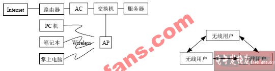
Figure 1 AP-based network structure Figure 2 P2p-based network structure
The network test is aimed at the problems that have arisen. In this paper, Jinjiang Hotel in Chengdu, Sichuan is selected as the test point. Its WLAN is based on the AP network structure, which is very representative. The WLAN coverage of Jinjiang Hotel includes the hotel lobby, Louvre Garden, Jinjiang Hall A, B, Four Seasons Hall, business center and other major places. The network topology is shown in Figure 3. The WLAN user terminal is connected to the AP through a wireless network card, and the AP is connected to the switch through a twisted pair cable. The microwave equipment is used to access the AC located in the mobile equipment room and then connect to the Internet.
2.1 External transmission test First, the basic performance of Jinjiang Hotel's WLAN network was tested, including wireless signal strength, integrated wiring quality, packet loss rate, bandwidth, etc. All indicators met the specifications.
1) Simulate that a large number of user terminals simultaneously initiate connection requests to the AC through the WLAN network and access the Internet. Some problems have occurred: some terminals cannot log on to the network; another part of the terminal has abnormally dropped after entering the network successfully. It is difficult for the terminal to obtain a network address after disconnection, and the obtained network address is easily aging. You need to manually release and obtain the network address, but the newly acquired network address also quickly aging. In order to collect data in sections, three test points A, B, and C are set up in the network, as shown in Figure 3.
2) When there is a problem with the terminal A that enters the network wirelessly, the terminal that uses wired connection directly to the switch to enter the network at point B has the same situation. Log in to the AC remotely and find that the access port repeatedly drops / up (DOWN / UP). The mode of the original AC access port was set to AUTO. As a result, the AC negotiated with the microwave device into a 100 M half-duplex working mode. If the mode of the AC access port is manually set to the 100 M half-duplex working mode, the port still repeatedly DOWN / UP.
3) Add a switch between AC and microwave equipment to enhance the adaptability to the interface of microwave equipment, while reducing the burden on AC. Switch port 9 is connected to AC and the port is set to 100 M full-duplex working mode; switch port 10 is connected to the microwave device and the port is set to 100 M full-duplex working mode. Under this network structure, the network situation of Jinjiang Hotel returned to normal, and no problems occurred. The terminal at point C can also enter the network normally.
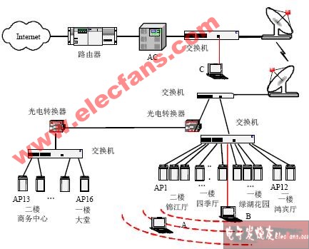
Figure 3 WLAN network structure of Jinjiang Hotel
2.2 Internal network test To test whether the AP's working status is stable, divide two VLANs on the switch. Make AP1 and AP2 in the same VLAN, and AP3 and AP4 in the other VLAN. Its structure is shown in Figure 4.
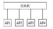
Figure 4 The connection between the switch and the AP
1) Use two terminals in DHCP (Dynamic Host ConfiguraTIon Protocol) mode, and the third terminal is configured in static network address mode to enter the network through AP1. Continue PING AP2 through AP1. It is found that the DHCP terminal occasionally goes offline, and the wireless connection status is still good when it is offline, but it cannot ping the gateway, and it needs to use authentication / refresh (CONFIG / RENEW) multiple times before it can be reassigned to the network address. At this time, the communication between the terminal with a static network address and AP2 is always normal.
2) Use two terminals to enter the network through AP1 through DHCP, and the third terminal is directly connected to the switch through a wired connection and enter the network through DHCP. It is found that both wireless users and wired users will have the phenomenon of disconnection, which shows that the problem of network disconnection is related to the backbone transmission quality and the upper layer protocol.
3) After the terminal switches from AP1 to AP3, the terminal cannot be assigned to a network address normally. Therefore, the terminal is configured as a static network address. Through the terminal of AP3 PING AP4, it is always able to communicate normally, which proves that both the wireless side and the wired side always work normally during the handover process.
4) In terms of mobile handover, let the terminal work in a place where the signal strength of the two APs is close. The terminal can keep a stable connection with an AP and will not switch arbitrarily. However, if you move the terminal to another area farther away and the original connection signal is weak, the terminal will automatically connect to the AP with the stronger signal. If the two APs are not in the same VLAN, the gateway cannot be pinged immediately after such a switch. At the same time, if it is a terminal that logs into the network through authentication, it cannot enter the network after switching, and must be re-authenticated. If the two APs are in the same VLAN, they can ping the gateway immediately after the switchover, and they can continue to enter the network.
3 Results and analysis According to the test data of the network, the problems that affect the network quality can be summarized as follows:
1) The working mode of the AC port cannot be completely matched with the microwave device, and the port mode of the microwave device also has inherent deficiencies. When a large number of users enter the network at the same time and there is a large amount of data traffic on the network link, the quality of the entire network will deteriorate due to transmission bottlenecks, and data packets will be dropped seriously, resulting in a decrease in network speed. At the same time, because the AC did not receive the online response packet returned from the terminal within the specified time, the network address allocated to the terminal was released, causing the terminal to go offline abnormally. Of course, the network address retention time can also be extended on the AC, but this will create a new problem. After the cross-VLAN switching, the old network address cannot be released and the new network address cannot be obtained.
2) The AP has a certain limit on the number of users who can access at the same time. Generally, it can provide reliable service for up to 30 users. However, the default setting of the AP at the factory is generally unlimited number of access users, so after the same AP access user reaches a critical state, if there is a new user access request, the AP will respond to the request due to hardware function Restriction discards a user who has established a connection, causing online users to go offline.
3) When the cross-VLAN channel switching is caused by user movement, the Internet access will be interrupted due to the MAC address conflict [4]. It is necessary to wait for a period of time before obtaining the network address and re-authenticate to the network.
Problems and Solutions in WLAN Engineering Construction
PACSystems* RX7i Controller
• Pentium® CPUs for your every need, from Celeron 300Mhz to M Class 1.8Ghz • VME64 Backplane provides up to four times the bandwidth of existing Series 90*-70 systems • 10/100 Ethernet built into the CPU, with easy cabling RJ-45 dual ports connected through an auto-sensing switch - no need for additional switches or hubs rack to rack • Up to 64MB memory for fast execution, storage of the complete program with all documentation (including Excel, Word, PDF and DXF files) - all in one CPU • Object Oriented programming through IEC languages including C for fast executing, standards based applications • Integration of Control Memory Xchange, a high speed global memory over a fiber network - like having a networked drive everyone can see and share • High capacity power supplies (100W and 350W) to reduce the requirement for an external supply
PAC Systems RX7i Controller,Turbine Control System,RX7i 17 Slot Rack,Speedtronic Mark IV Turbine
Xiamen The Anaswers Trade Co,.LTD , https://www.answersplc.com