
Frequency modulation wireless microphone circuit with voltage stabilizing circuit
To introduce you to a wireless microphone with a simple structure and a transmission distance of more than 200 meters. General beginners can make it successfully.
First, the circuit principle (see the following figure) The circuit consists of three parts: 1. Audio amplification part; 2. High frequency oscillation part; 3. Voltage regulation part. The signal is injected into the base of the transistor VT1 by the microphone MIC, and the audio signal amplified by VT1 is coupled to the base of the high-frequency oscillation circuit VT2 through C2, and then transmitted through the antenna. The operating frequency of this circuit is between 85 and 104MHz.
Second, the selection of components MIC selects a highly sensitive electret microphone, VT1 is 9013H, β≥125. VT2 is 2N3866; β≥90, ∮0.71mm enameled wire of L1 and L2 is closely wound on the ordinary ballpoint pen core by 4 turns and 10 turns, C4, C5 and C6 use ceramic capacitors, the error is ± 5%. The three-terminal regulator uses LM7806 power supply, 9V battery, and the circuit board can be self-made.
3. Assembly and debugging The circuit assembly is relatively simple, as long as the components are not damaged, one assembly can be successful. After the circuit is welded, the antenna is welded up again. The antenna uses a 0.5-meter radio antenna. Place the microphone at the sound source during debugging. Then, leave the microphone 5 to 6 meters away, turn on the FM radio, and adjust the channel selection knob. The turbid harmonics are received, and the pitch of the oscillating coil L1 can be adjusted with a screwdriver. The frequency increases when the pitch of the L1 is large, and vice versa. At this time, the received harmonic is not a sound.
If you want to increase the transmit power, you can change the length of the transmit antenna, or replace the VT2 launch tube with a 34D50 triode, and the R4 resistance with 4.7kΩ. At this time, the launch distance can be increased by about 100 meters. 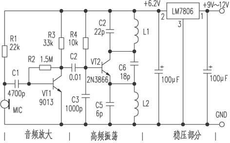
The PufangTech`s wireless data modem is used to replace standard RS232 and RS485 serial communication cables. It provides a transparent connection between source and destination terminal and requires no knowledge of the data it is transmitting and the data can be simply sent and received with minimal delay.
With 12.5KHz channel spacing, the over-air transmission adopts different modulation scheme to meet various air rates. For air rate below 1200 bps, modulation scheme of FSK is used. For air rate of 1200, 2400 or 4800bps, MSK or FFSK modulation scheme is used. At 8000bps air rate, GMSK modulation scheme is adopted and at 9600bps air rate, the modulation is 4-level FSK. With 25KHz channel spacing, GMSK modulation scheme can support air rate of 16000bps and 4-level FSK can support 19200bps.
PufangTech`s wireless modem can make very beneficial and value added agreements with distributors and system integrators.
Wireless Data Modem,Wireless Radio Modem,Long Range Wireless Modem,Digi Wireless Modem
Shenzhen PuFang Technology Co., Ltd. , https://www.hytelus.com