
Abstract: This article explains how to use the DS1841 log potentiometer to adjust the output range of the APD bias circuit. In order to make the adjustment process easier, this article also provides a spreadsheet.
The APD bias circuit DS1841 temperature-controlled non-volatile (NV), I²C log potentiometer contains a 7-bit log-varying resistor. By working with a boost DC-DC converter, the DS1841 can adjust the bias voltage applied to the avalanche photodiode. Three external resistors (RSER, RTOP, and RPAR) are used to adjust the output range (Figure 1).
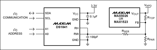
Figure 1. APD bias circuit using DS1841 and a boost DC-DC converter (here MAX5026 or MAX1523)
Adjusting the APD bias voltage range Use the electronic data sheet DS1841 APD bias voltage adjustment (xls) to easily adjust the APD bias voltage. The spreadsheet contains four input variables: RTOP, RSER, RPAR, and VFB. After entering these resistance values, the spreadsheet can calculate four output values: VAPD (maximum value), VAPD (minimum value), STEP (maximum value), and STEP (average value). In addition, two graphs are generated: the curve of the relationship between the APD offset and the DAC code and the graph of the relationship between the voltage of each stage and the DAC code. The interface shown in Figure 2 shows the four variables and the graphics generated by entering the values. Table 1 defines the parameters used in the spreadsheet.
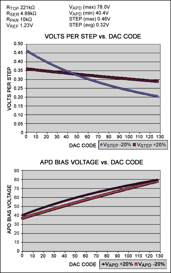
Figure 2. The spreadsheet interface contains four data input variables (see upper left corner)
Table 1. Variable definitions when using DS1841 to adjust the APD bias voltage range
The APD bias circuit DS1841 temperature-controlled non-volatile (NV), I²C log potentiometer contains a 7-bit log-varying resistor. By working with a boost DC-DC converter, the DS1841 can adjust the bias voltage applied to the avalanche photodiode. Three external resistors (RSER, RTOP, and RPAR) are used to adjust the output range (Figure 1).
Figure 1. APD bias circuit using DS1841 and a boost DC-DC converter (here MAX5026 or MAX1523)
Adjusting the APD bias voltage range Use the electronic data sheet DS1841 APD bias voltage adjustment (xls) to easily adjust the APD bias voltage. The spreadsheet contains four input variables: RTOP, RSER, RPAR, and VFB. After entering these resistance values, the spreadsheet can calculate four output values: VAPD (maximum value), VAPD (minimum value), STEP (maximum value), and STEP (average value). In addition, two graphs are generated: the curve of the relationship between the APD offset and the DAC code and the graph of the relationship between the voltage of each stage and the DAC code. The interface shown in Figure 2 shows the four variables and the graphics generated by entering the values. Table 1 defines the parameters used in the spreadsheet.
Figure 2. The spreadsheet interface contains four data input variables (see upper left corner)
Table 1. Variable definitions when using DS1841 to adjust the APD bias voltage range
| VFB | The voltage present at the feedback node of the DC-DC converter. |
| VAPD (max) | The maximum voltage to which the APD bias can be set under worst-case condiTIons. |
| VAPD (min) | The minimum voltage to which the APD bias can be set under worst-case condiTIons. |
| STEP (max) | The maximum calculated voltage step that can occur between two adjacent DAC codes. |
| STEP (avg) | The average voltage step size that occurs across the full range. |
| VSTEP + 20% | The voltage step size when the variable resistor is at the maximum of the process range (+ 20%). |
| VSTEP -20% | The voltage step size when the variable resistor is at the minimum of the process range (-20%). |
| VAPD + 20% | The APD bias voltage when the variable resistor is at the maximum of the process range (+ 20%). |
| VAPD -20% | The APD bias voltage when the variable resistor is at the minimum of the process range (-20%). |
LED Tunnel Lamp is an attractive, functional and weather-resistant feature.Tunnel lamps and lanterns;Die casting aluminum process and aluminum alloy forming process;Strong structure and strong impact resistance;The heat dissipation performance can guarantee the permanent work of lamps in the harsh working environment of the tunnel.Efficient and reliable constant current.Power supply can make lamps work stable and live longer;This lamp also can serve as gas station illume, charge.Station lighting and other ceiling working environment.

Led Tunnel Lamp,Rapidcure Led Tunnel Lamp,Smart Tunnel Led Lamp,Led Lamp
Jiangsu chengxu Electric Group Co., Ltd , http://www.chengxulighting.com