
RS422A is a standard interface for bidirectional, differential balanced drive and receiving transmission lines widely used in the industry. It communicates in full duplex mode, supports multipoint connections, allows the creation of networks of up to 32 nodes, and has a long transmission distance (maximum transmission distance 1200m), fast transmission rate (100kbit / s at 1200m) and other advantages, compared with other buses, such as FF, CAN, LonWorks, etc., has a simple structure, low cost, easy installation, compatible with traditional DCS and other characteristics In addition, many field instruments on the market have RS422A bus interface, so using this bus can easily develop some small and medium-sized network measurement and control systems. The RS-422A bus is the "Electrical Characteristics of Balanced Voltage Digital Interface Circuits" published by the EIA. This standard was developed to improve the electrical characteristics of the RS-232C standard while considering compatibility with RS-232C. Combined with the actual characteristics of a certain project, we adopted RS422A communication interface to realize the remote data communication system.
In this project, the system uses a two-level master-slave bus network structure. The control of temperature and other variables is mainly realized by each intelligent instrument on the bus. The host computer modifies the parameters such as the given value of the intelligent instrument according to the control requirements, and the monitoring and display of some digital quantities. The intelligent instrument selected for this project is produced by Shanghai Dahua-Qianye Instrument Co., Ltd. The parameters are quite complex, with strong control and communication functions. At the same time, the use of rich software and hardware resources of the host computer, with Windows as the operating platform, so the application software developed has powerful management functions and a very friendly man-machine interface. The application software of this system is developed with Microsoft Visual C ++ 6.0, fully utilizes VC ++ to be flexible and fast, and has a convenient interface for window programming and multi-task programming. The developed software has perfect functions of data collection, setting, alarming, real-time monitoring and so on. The application results show that the system effectively monitors the temperature control system with good results.
system structure
The intelligent instrument has relatively complete functions and high control accuracy. Comes with RS422A communication card, up to more than 100 communication commands, large amount of uploaded and received data, mainly including temperature setting value, PID parameter value, alarm parameter value, sensor correction value, fuzzy control parameter value, etc. The field bus adopts RS422A bus, because RS422A bus has the advantages of simple structure, low cost and convenient installation. The intelligent instrument is connected to the RS422A bus and connected to the PC serial port through the RS422A / 232C changer. To this end, there are more than a dozen (expandable) smart meters, an RS422A / 232C converter, and each meter is set with a unique address. The temperature control is completed by the lower computer (intelligent instrument). The functions completed by the main control computer include 1) actively reading the relevant data of the lower computer 2) changing the temperature control settings and other parameters, but not directly controlling the temperature. 3) Display the temperature control curve screen, the temperature controller centralized display screen and the dynamic display of alarm data and so on. 4) Data storage, statistics, reports, etc. The hardware structure of the system is shown in Figure 1.

Figure 1 System hardware structure diagram
letter of agreement
1) The physical layer uses a balanced standard RS422 interface to improve the reliability of data transmission. In the balanced standard RS422A,
Both the transmitter and the receiver work in a differential manner. Each signal is transmitted by two wires, and the signal level is represented by the difference between the signals on the two wires.
2) Data link layer This system uses asynchronous serial communication. The system agreed that the baud rate: 9600bps, even parity, 1 start bit, 7 data bits, 1 stop bit, using ASCII code as the transmission code. The transmission frames on the bus are divided into command frames and data frames. The command frame is further divided into an address command frame containing address information for establishing a connection and a control command frame that requires uploading or downloading data for the established connection. The text format of the latter and the data frame is as follows:

3) The network layer realizes the function of this layer protocol by PC. In the transmission frame on the bus, the address command frame is sent by the control PC in the form of broadcast, used to wake up a certain instrument on the bus, shake hands to establish a communication relationship with it, and then the corresponding instrument returns the machine to the control PC Address, the handshake is successful; otherwise the meter returns a negative response to the PC. When the PC wants to communicate with other instruments other than the currently communicating instrument, it must first abandon the current communication relationship and send an abort communication command frame. Then re-establish the connection as described above. The format of establishing a connection, abandoning the connection, and the response of the temperature controller are as follows:
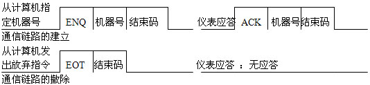
Among them ENQ, EOT, ACK is the control code end code, which means the end of a frame
4) Application layer The application layer of the RS422A bus network system of industrial intelligent instruments is to frame the information transmitted between the control PC and the intelligent instruments, that is, the data format is defined according to a certain format and meaning.
System software design
The system management software adopts object-oriented technology, is based on the Windows2000 platform, and is developed with VC ++ 6.0 programming. The system application software is composed of two parts: real-time dynamic process and historical record browsing. The real-time dynamic process consists of three modules: data acquisition and setting, operation control, and data management. And setting process real-time data. The control module is mainly used to control the operation or stop of the instrument and the selection of the operating section. The data management module includes data communication, data display, alarm, printing, storage and other functions.
According to the characteristics of the real-time system, multiple tasks in the monitoring software are running at the same time. In order to prevent one task from executing while blocking other tasks, we fully included the characteristics of the Windows system that allows multi-process and multi-thread programming, and divides the system into Modules. First, the historical record browsing and real-time dynamic process are divided into two processes, because these two processes are very different. The data in the historical record browsing is static, there is no requirement for real-time, and it can be run during or after the production process. When developing this part of the program, you don't need to consider the issue of time. The real-time dynamic process is a task with high real-time requirements. In this process, the tasks of communication, display, control, and printing are mainly completed, and the data dump is also completed.
(1) Dynamic process design
The term thread refers to the sequential execution of program instructions. Each program independently executes a series of instructions in the program code. From the perspective of user or application programming, the threads in the program run simultaneously. Operating systems usually rely on the rapid switching control of thread and line contractors to achieve this simultaneous feeling (but if the computer has multiple processors, the system can directly execute threads simultaneously). When a program needs to complete multiple tasks at a certain time (as many reference programs do), placing each task in a different thread not only makes the program more efficient, but also simplifies development.
When designing a real-time dynamic process, we divided it into two threads: the main thread and the communication thread. The main thread starts the communication thread regularly, and the communication thread automatically hangs after executing a communication task. Under normal circumstances, the time between the main thread resuming the communication thread is to ensure the complete execution of the communication thread.
In terms of data storage, in order to improve the dynamic performance of the system, it is required to quickly access the data storage area. We store the data in two places. The process data of the ongoing production process is first stored in the data buffer created in the memory, so that the main thread can quickly access it. In addition, the data of several communications is regularly stored on the hard disk, which can prevent the loss of data due to accidents such as power outages.
In program design, we adopted the idea of ​​object-oriented design. For example, we regard the temperature controller as an object. The related data structure and its operation are completely encapsulated in a class, so that the separation of the program's data structure can also be separated For software expansion, it will bring great convenience for software development and debugging.
The main implementation of the software is as follows:
Call the custom function StartOfSystem (pDC) in the overloaded void CRS422AnetView :: OnDraw (CDC * pDC) function. The latter opens and configures the serial port, starts the communication thread, and sets the timer. The main code is as follows:
void CRs422AnetView :: StartOfSystem (CDC * pDC)
{
...
m_hCom = CreateFile (m_sPort, GENERIC_READ | GENERIC_WRITE, 0, NULL,
OPEN_EXISTING, FILE_ATTRIBUTE_NORMAL | FILE_FLAG_OVERLAPPED, NULL);
if (m_hCom == INVALID_HANDLE_VALUE)
return FALSE;
DCB dcb;
if (! GetCommState (m_hCom, & dcb)) return FALSE;
dcb.fBinary = TRUE;
dcb.BaudRate = m_nBaud;
dcb.ByteSize = m_nDataBits;
dcb.fParity = TRUE;
dcb.Parity = EVENPARITY;
dcb.StopBits = ONESTOPBIT;
return SetCommState (m_hCom, & dcb);
...... // The above is to open and configure the serial port code
SetTImer (1,5000, NULL); // Start the timer, the timing interval is 5 M
CwinThread * m_pThreadd = AfxBeginThread (CommProc, this-> GetDocument (), THREAD_PRIORITY_NORMAL, 0, CREATE_SUSPENDED, NULL); // Create and suspend the thread
if (m_pThreadd == NULL)
{
CloseHandle (m_hCom);
return FALSE;
ï½
else
{
m_bConnected = TRUE;
m_pThreadd-> ResumeThread (); // Resume thread operation
ï½
...
ï½
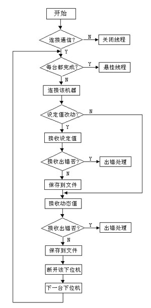
UINT CommProc (LPVOID pParam) is an auxiliary communication thread. This thread completes the reading of set values ​​and dynamic data. The program flow chart is as follows:
void CRS422AnetView :: OnTImer (UINT nIDEvent) is a function that responds to the timer message, the timing is triggered, the timing interval in this program is 5 seconds. In this function, it is mainly to restore the auxiliary communication thread, call the data display program, and refresh the data regularly.
(2) Design of browsing process of historical records
The browsing of historical records is to review the past production process, which can be combined with the product quality and process settings for analysis, to provide reference for future production, so as to improve the production quality of products. This process provides a certain query function, which can play back historical records in a curve way, can lock important processes, and can also delete process records.
The temperature-controlled network system based on RS422A field bus introduced in this article has been operating on site for a long time. The system runs stably and reliably, giving full play to the convenient advantages of network management and improving production efficiency. Obviously, for some small and medium-sized measurement and control systems, using RS422A is a good choice.
High Power High Voltage Power Supply
Hv Power Supply,High Voltage Power Supply 100Kv,Adjustable High Voltage Power Supply,Adjustable High Voltage Power Supply
Yangzhou IdealTek Electronics Co., Ltd. , https://www.idealtekpower.com