
Design of remote six-channel remote control codec transceiver system
In recent years, remote control technology has become more and more widely used in industrial production, household appliances, security, and people's daily lives. In the field of wireless remote control, currently commonly used remote control methods mainly include ultrasonic remote control, infrared remote control, and radio remote control. Since the radio wave propagates from the launch point to all directions, can pass through the barrier, and can spread to a long distance, so its control can be realized in a large area and space, so it has become the main method of remote control. There are a wide range of applications in national defense, military, production, construction and daily life. The long-distance remote control codec transmit and receive components are high-power transmitters (transmitting power 2 to 5 W) that use digital coding chips as modulation signals, and are equipped with high-sensitivity receivers (receiving sensitivity is not worse than 1.5 μV) and coding The chip-paired decoding circuit can complete long-distance wireless remote control, signal transmission, and alarm. The remote control switch system designed by this method is convenient to control, suitable for occasions with more controlled electrical appliances, and can realize multi-channel multi-function control.
1 System chip selection The main chips used in this system are the radio frequency transmitting chip MI-CRF102 and the radio frequency receiving chip MICRF022, as well as the coding chip PT2262, decoding chip PT2272, main control chip AT89C2051 and so on. This article mainly introduces MICRF102 and MCRF022.
1.1 The functional characteristics of MICRF102 chip The chip MICRF102 adopts the latest rapid wireless transmission technology of Micrel Company, which can realize the true "data input, wireless output" function. MICRF102 adopts a new structure to tune all external antenna loops to the internal UHF synthesizer. All of its tuning can be automatically realized in the IC, so you can eliminate the trouble of manual tuning. The MICRF102 has a simple structure and requires very few external components, which is very convenient to use.
The main electrical parameters of MICRF102 are as follows:
â—‡ Working voltage 4.75 ~ 5.25 V:
â—‡ Working current 4.7 mA;
◇ The frequency range is 300 ~ 470 MHz;
â—‡ Data transmission rate can reach 20 kbps;
◇ Standby current is not more than 1μA.
The MICRF102 is packaged in an 8-lead SOIC. Figure 1 shows the pin arrangement.
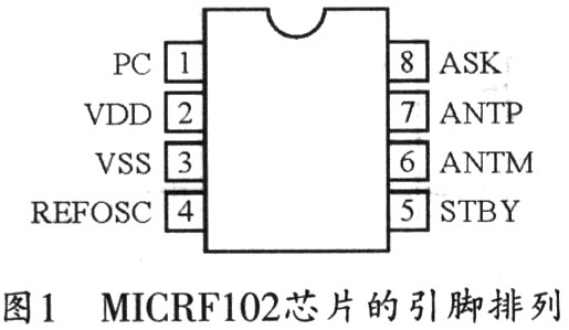
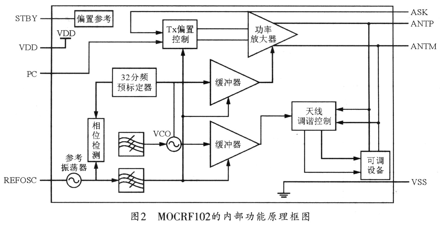
Figure 2 is the internal functional block diagram of MOCRF102, which is mainly composed of UHF synthesizer, buffer, antenna tuner, power amplifier, TX offset control, offset reference and adjustment circuit.
1.2 The characteristic function of MICRF022 chip The radio frequency receiving chip MICRF022 is an enhanced receiver of the chip MICRF001. It adds standby and wake-up functions on the basis of MICRF001. MICRF022 has 2 operation modes: fixed mode (FIX) and scan mode (SWP). The fixed mode is the conventional superheterodyne receiving mode, which can provide better selectivity and sensitivity; the scanning mode uses a wide RF spectrum patented technology, which can receive low-cost and inaccurate transmitted signals.
The electrical parameters of MICRF022 are as follows:
◇ Working frequency is 300 ~ 440 MHz;
â—‡ Using ASK / OOK demodulation method;
â—‡ Receive sensitivity is -95 dBm (433.92 MHz);
â—‡ Data transmission rate is 10 Kb / s (fixed mode);
◇ Working voltage is 4.75 ~. 5.5 V;
◇ Working current is 2.2 mA (315 MHz), standby current is 0.9μA.
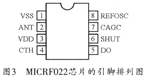
The MICRF022 is packaged in an 8-lead SOIC. Figure 3 shows the pinout of the MICRF022.
2 System composition and working principle The entire system is composed of two parts: a transmitting system and a receiving control system. The composition and working principle of the system are shown in Figure 4.
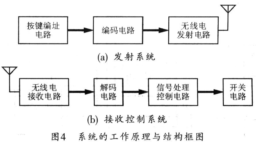
When the system is working, first input the bit number of the required control circuit through the key addressing circuit, and at the same time start the encoding circuit. The instruction encoding circuit will generate an encoded pulse signal with address encoding information and switch status information under the control of the internal circuit. The signal modulates the radio transmission circuit, and then transmits the signal through the radio transmission circuit. The radio receiving circuit can confirm the encoded address of the coded pulse signal received by the (b) receiving control system through the decoding circuit to confirm whether it is the address of the remote control switch system. If it is, the received signal is decoded, and at the same time, the instruction decoding circuit outputs a valid data signal, and the corresponding control instruction is issued through the signal processing control circuit and the control logic. If it is not, the decoding circuit does not decode, nor does the instruction decoding circuit decode, the signal processing control circuit does not respond, and the switching circuit has no action.
3 System hardware circuit design
3.1 Transmitting module circuit The transmitting system is mainly composed of key addressing circuit, coding circuit and radio transmitting circuit. The schematic diagram of the module circuit of the transmitting system is shown in Figure 5. The main function of the transmitting system is to address the switch of the controlled circuit first, and then encode the addressing information to obtain an encoded pulse signal, from which the signal remodulates the radio transmitting circuit and transmits it.
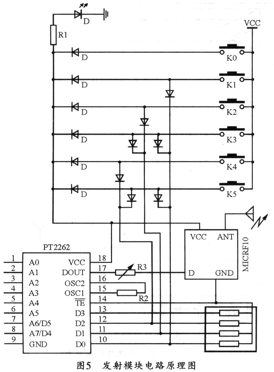
The key coding circuit uses a diode combination logic switch array to address the controlled circuit switches, in which the command coding circuit uses a coded chip set PT2262. Port A of PT2262 is an address code setting port, and port D is a data code setting end, respectively connected to the logic output of a diode combination logic switch array, and the data has six states from 000 to 101. The radio frequency chip used in the transmitter module circuit is MICRF1020. When there is no signal output from the data output terminal of the encoding chip PT2262, the MICRF102 does not work, and the transmission current is zero. When the control terminal of the PT2262 is valid, the output serial pulse signal is carried out To modulate the transmission, the transmission current can be adjusted through the modulation resistor R2, thereby adjusting the transmission distance. The smaller value of R2 can increase the transmission distance, and the addition of a diode switch array can expand the system into a multi-channel remote control transmission module.
3.2 Receiving control circuit The receiving control system is mainly composed of a radio receiving circuit, a decoding circuit, a single-chip circuit, and a switching circuit. The circuit schematic diagram of the receiving control system is shown in Figure 6. The main function of the receiving control system is to demodulate and decode the received signal, and send the decoded data to the single-chip microcomputer, and the single-chip microcomputer will control the corresponding switch to act according to this data.
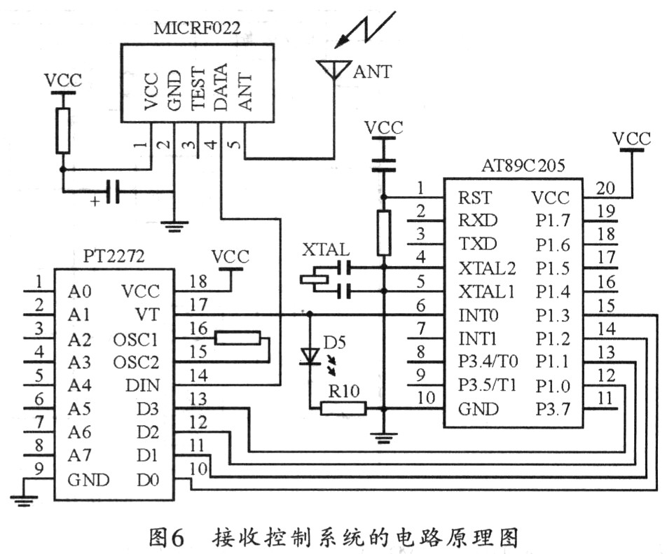
The receiving control circuit is mainly composed of a radio receiving circuit, an instruction decoding circuit, a signal processing and control circuit and a switching circuit. The radio receiving circuit is realized by the radio frequency receiving module MICRF022 matched with the radio frequency transmitting module MI-CRF102. The MICRF022 has a wide receiving bandwidth, extremely low power consumption, and can be in a standby state for a long time. The output port of MICRF022 is directly connected to the data input port of the decoding chip PT2272. When the address code of the receiving end and the address code of the transmitting end are set exactly the same, the output end of the decoding chip only has an output signal to connect the output signal with the radio transmitting circuit The corresponding switch information is sent to the signal processing control circuit, and the control circuit controls the corresponding switching action. Otherwise, the decoding chip does not decode, the signal processing control circuit does not respond, and the switching circuit does not have any switching action. The signal processing control circuit adopts AT89C2051 single-chip microcomputer to realize the processing of the input signal and the control of the switch circuit.
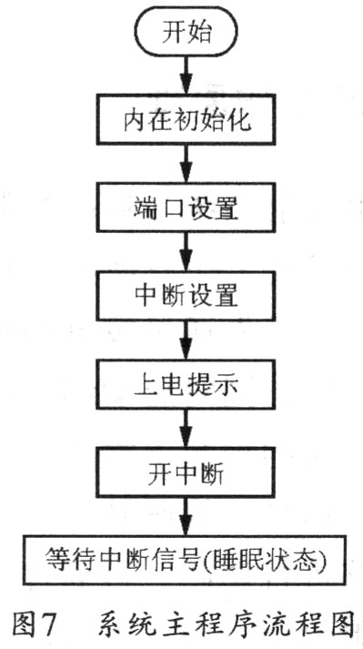
4 system software design The main program flow chart of the single chip microcomputer in this system is shown as in Fig. 7. The design of the system software is to realize the state and control of the switch circuit by the single chip AT89C2051 through programming. SCM samples the effective interrupt request signal, and then executes the interrupt service subroutine. In the interrupt service subroutine, the single chip microcomputer will execute the corresponding subroutine according to the data obtained by the I / O port, so as to realize the control of the controlled circuit. Making full use of the software and hardware resources of the single chip microcomputer can realize the control of various states of the controlled circuit, and can also use a single key to control the multi-circuit circuit.
5 Conclusion This system is mainly for the design of remote six-channel remote control codec transceiver system. The system has been fully debugged in the laboratory. The results of hundreds of operation experiments show that the data transmission is accurate and the performance is stable. This design is suitable for the development of various low-cost remote control alarms and various remote control systems, such as remote control of household appliances, remote control of electrical appliances in cultural and educational entertainment venues, and remote control of electrical appliances in office places. The application of this system can not only bring a lot of convenience to people's work and life, but also has a good value of promotion and application.
Warning Lights are generally used to maintain road safety. They are usually used in police cars, engineering vehicles, fire engines, ambulances, maintenance management vehicles, road maintenance vehicles, tractors, emergency A/S vehicles, mechanical equipment, etc., machinery, electricity, Control signals interlocking in electrical control circuits such as machine tools, chemicals, telecommunications, ships, and metallurgy.
For Warning Lights,we have our own research and development team,we are always committed to providing the best service to all clients,in our company,the Warning Light are mainly divided into these series:
BPT5 Bulb/LED Tower Light
BPTL5 Bulb/LED Tower Light
BPT7Z Bulb/LED Tower Light
B-2071 Mini Warning Light
B-1101 LED Warning Light
B-TYN Solar LED Warning Light
B-1101ROG Multiple Colors LED Warning Light
MS190 290 390 Sirens
Buzzers
Warning Lights
Warning Lights,Tower Light,Warning Lamp,LED Tower Light
Ningbo Bond Industrial Electric Co., Ltd. , https://www.bondelectro.com