
Overview An audio alarm signal is issued when the light beam is blocked, from which a large number of interesting applications can be imagined. This application note describes one such system. Using the MAXQ3210 microcontroller and the built-in piezoelectric speaker / transducer driver, only a few external components are needed to implement this system.
The photoelectric sensor module on the market can be used as the input of the alarm system. There are many types of light sensors. This article discusses how to choose the best sensor for a specific application. A wall adapter is used to power the system.
The MAXQ3210 RISC microcontroller is the core of the system and requires few peripheral devices. A small 3-pin piezoelectric audio speaker is used to generate an alarm; all electronic circuits are powered by a linear regulator, and only the photoelectric module is directly powered by an external power supply. Figure 2 shows the schematic of this system. A two-layer printed circuit board (PCB) is used for system wiring, and the Gerber file of the (ZIP) PCB can be downloaded. The file also includes source code, corresponding project files, and loadable hex files for this application.
The development software of this system is written in MAXQ® assembly language, and the development tool is MAX-IDE version 1.0. MAX-IDE provides a free development environment based on Windows® and provides a complete set of development tools for MAXQ series processors.
The firmware development for this application is based on the MAXQ3210 evaluation board hardware platform. The evaluation board provides a convenient and reliable platform for verifying firmware. Evaluation boards and MAX-IDE tools provide a complete development and debugging environment.
Application anti-theft alarm is a common application of the beam alarm system introduced in this article. When intruders pass through the entrance channel protected by the light sensor, they will block the light beam, thereby triggering an alarm. If there are very few impurities that cause light reflection in the air, the beam is invisible, so the beam is blocked before the intruder realizes that the sensor is alarming. Such a system can be used to notify people on duty at the mall that someone has entered. Sensors can also be used to monitor someone or something (such as an area where pets are located). Place the sensor at the entrance of this area, the light beam will not be noticed by people until it is blocked. For example, if the sensor is placed on a kitchen workbench, the alarm sound can prevent household pets from jumping on the workbench.
In shopping malls, this alarm system can be used to detect items on a running conveyor belt. Put the receiver or reflector in a relative position, an alarm will sound when an object passes through and blocks the beam. If the items on the conveyor belt vary in size, the sensor can be set to block only the largest item. For a more complex system, different sensors can be distinguished by installing different sensors at different heights of the conveyor belt. If the objects are large enough and have enough reflection intensity, then they can reflect enough light intensity to the receiver to trigger the sensor. With minor changes to the software, the alarm system can be modified to trigger an alarm when the conveyor belt stops, and can even be used to count items.
It can be seen that the beam alarm system has a wide range of applications, and various applications greatly exceed the imagination of users. The alarm system introduced in this article is a universal design, suitable for many occasions, and it can also be used to complete a more unique system for a specific application.
Photoelectric sensor In the photoelectric sensor, the light source and the emitter will generate a beam of light signal that can be detected by the photosensitive device, ie the receiver. The light source is usually an LED module, which is packaged with the driving circuit and the optical part. The receiver contains amplifying and demodulating circuits and related optical receiving circuits. In order to adapt to the application of different occasions, the modules sold on the market have many types of configurations. For example, sensors can be designed to trigger an alarm when there is an object or when there is no object; they can be designed to trigger an alarm by surface reflection of a specific type (rather than any type); they can focus on very fine objects, such as a thin line It can also cover large areas or large-sized objects by scattering. Such a wide range of applications requires designers to choose photoelectric sensors carefully. The following discusses some factors that affect sensor selection.
Detection mode The detection mode of the photoelectric sensor is generally divided into three types: through-beam, retro-beam, and scatter. Through-beam mode detection is also called "light transmission". The light transmitter and receiver are located in different packages and placed in opposite positions. The light beam from the transmitter directly enters the receiver. It is detected when an object blocks the light beam. In the retroreflective mode, an object intrusion is also detected when the beam is blocked. But in this mode, the transmitter and receiver are in the same package. A special reflector (retroreflection) returns the beam from the transmitter to the receiver. The mirror can only reflect the light beam to the light source when it is perpendicular to the light beam. The retroreflective device can reflect the light beam to the light source regardless of the angle of incidence (of course, there are certain restrictions). This single package configuration combines the electronic circuits of the retroreflective sensor together, reducing one package and the accompanying cables. Scatter detection is also called proximity mode. The transmitter and receiver are located in the same package, but the light beam is reflected by the detected object. This mode is usually used when the target has strong reflection and the reflection surface is large enough, so that most of the emitted light is reflected to the sensor.
The optical devices used in a particular sensor will significantly affect the effectiveness of the specific application. The typical scattering detection mode uses a minimum of optics to obtain a broad emission template, and the receiver also has a wide viewing angle. A special case is the focus mode detection, which requires the use of another optical device to generate a focused beam, limited to an accurate detection area. This method can detect objects when they do not have enough reflection intensity. If space is limited, optical fibers or fiber beams can be used to conduct optical energy between the transmitter and receiver. Optical fibers can also be used when objects need to be detected in a highly corrosive environment, because glass, which is usually used as a fiber material, can withstand higher temperatures and has strong corrosion resistance, far superior to photoelectric sensors.
Sensor output Another significant feature of the photoelectric sensor is the output type. Depending on the device configuration, the receiver can generate an effective alarm output when a light beam is detected ("with light") or when the light beam is detected to disappear ("no light"). When the receiver outputs an alarm, it can be pulled up to the power supply voltage (source current), called "PNP output", or pulled down to ground level (sink current), called "NPN output". Some devices provide user-selectable detection with or without light, and have PNP and NPN outputs.
The color or wavelength of the emitted light of the wavelength sensor is also a significant feature. The sensor can be selected for a specific application according to the wavelength of the emitted light. The object to be measured may have strong reflection or absorption capabilities at a certain wavelength. Most standard sensors use wavelengths at the high end of the visible light spectrum (red light = 650nm) or the low end of the infrared spectrum (infrared light = 880nm).
In order to reduce the influence of interfering light sources, the light sources are usually modulated. Then apply the modulated signal to the receiver to filter out the excess signal. The typical modulation frequency is a few kilohertz, this frequency will directly affect the response time of the system.
The effective distance from the photoelectric sensor is several centimeters to hundreds of meters. The distance of the retro-reflection detection mode is usually 10 times that of the retro-reflection or scattering mode detection. Some transmitters use a lens to calibrate the beam, for example, to make the beam parallel and increase the beam density, thereby increasing the detection distance. Some emitters use the natural scattering properties of light to cover a larger area. However, due to scattering effects, the detection distance of such transmitters is generally shorter. In general, the effective detection distance of a retroreflective detection system is four times that of a simple reflection architecture. When you need to detect a long distance, you can use a laser source. Because the laser has minimal beam spread when it is emitted, most of the energy of the transmitter is returned to the receiver. In some applications, the reflecting ability of the surface of the object to be measured is strong, and a polarized reflector can be used. In this case, any unpolarized light returning to the sensor is the reflected wave of the object to be measured.
Additional gain Any photoelectric sensor has a key indicator, that is, additional gain, used to estimate the reliability of the sensor in a specific environment. In particular, this parameter is also an indicator to measure the sensitivity of the receiver, that is, the ability to detect a signal with a light energy higher than the minimum threshold and generate an effective alarm output. The additional gain ranges from a clean air environment, 1.5 when there is no dust on the lens and reflector, to a dirty environment, where there is a lot of smoke, fog, or dust pollution 50 or more.
System sensor example The photoelectric sensor used in the example given here is Keyence â„¢ PZ-G61B. Figure 1 shows the sensor, PCB and transmitter. The sensor is designed for retroreflective inspection in many different applications. The sensor provides user-adjustable gain, while providing PNP and NPN output alarm signals. In this example, when an alarm is triggered, the PNP output switches the module power supply (+ 12V DC in this example) to the output. The sensor also provides a user-selectable double-throw switch, which is used to set no light or light alarm. In this application, the sensor is set to no light alarm. Using a specific reflector, the effective detection distance of Keyence PZ-G61B is 0.3 feet to 13.8 feet (0.1m to 4.2m). In the example, the reflector is Keyence OP-84219 R-2L, 2in x 2in retroreflective area.
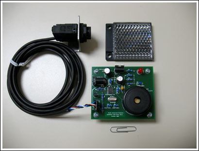
Figure 1. PCB, sensor and transmitter
Circuit block diagram The circuit block diagram of this design is shown in Figure 2. In the figure, the system built with the PZ-G61B sensor and the MAXQ3210 microcontroller requires few external components. The 12V wall adapter powers the system. Because the sensor and the microcontroller have different power supply requirements, another regulator was selected. The specified power supply of the photoelectric sensor is: 10V to 30V DC ± 10%, and the maximum power supply voltage of the MAXQ3210 is 9.5V. Using two devices with the same power supply will allow the specified specifications to be reached without any margin. Therefore, a voltage regulator is used on the PCB to generate the 5V power supply of the microcontroller. The 5V linear regulator (7805) can reduce the external 12V power input to the 5V required by the microcontroller. The internal voltage regulator can be disabled by shorting the MAXQ3210's digital power input (VDD, pin 17) and regulator output (REGOUT, pin 18).
When conducting prototype testing, it is necessary to note that an unregulated power supply is used in this solution, and the output voltage listed in the bill of materials is significantly higher than the nominal value of 12V. At no load, the output voltage is approximately 16V. Because 16V is still far below the maximum rating of the 5V regulator, it will only cause the regulator to heat up a little at full load. Because there is no enclosed voltage regulator, it is in an exposed environment, so for this application, heat generation is not a problem. However, under special circumstances, heat dissipation may need to be considered. Adding a heat sink to the TO-220 voltage regulator package can solve this problem. It is also possible to use a more stable 12V power supply. Since the power consumption of the circuit board is very low, either way will ensure that the temperature of the 5V regulator is within the specified range.
In this design, the output of the photoelectric sensor is buffered by the n-channel FET and enters the input pin of the microcontroller. In this way, the microcontroller can be protected from ESD impact introduced by the remote sensor cable into the circuit board. If there is indeed a destructive ESD impact, the FET may need to be replaced instead of the microcontroller. This buffer protection only requires a very low cost, and can also obtain the additional benefit of being able to isolate the 12V sensor output signal from the 5V signal level that appears on the microcontroller input pin.
To generate an audible alarm, the system uses CUI CEP-1172 piezoelectric audio speakers. The minimum sound pressure level of the device is 81db (30cm, 12V DC power supply), and the resonance frequency is about 3.3kHz. Because the MAXQ3210 in this system generates a speaker drive signal close to 5V, the speaker will generate a high alarm sound, enough to attract people's attention. Coupled with several passive components (two resistors and a capacitor), the MAXQ3210 can produce a noticeable sound level.
Figure 2. Schematic of the circuit board
Firmware detailed description The firmware in this application is very simple, including hardware initialization, main program loop and several subprogram assembly source files (LightBeamAlarm.asm). The PNP output of the light sensor is connected to the P0.0 port of the processor through the FET, and the signal level is read by the software. If the sensor outputs an alarm, an alarm will sound.
In order to generate an alarm sound, the subroutine will put the piezoelectric speaker in an "intermittent" state and drive the speaker for a fixed on and off time. The opening and closing time can be determined according to the experiment, and the alarm sound that can attract people's attention as much as possible is subjectively selected. Regardless of whether the light sensor output alarm signal is short, the speaker will intermittently emit five cycles of alarm. If the alarm output time of the sensor is longer than five intermittent cycles, the speaker will continue to generate another five alarm cycles until the sensor alarm is released.
As an indicator of "system health", an LED will flash. Use the high current drive capability of the P0.7 pin of the processor to directly drive the LED. The timer 2 of the processor generates a timeout alarm every 0.5s and generates a corresponding interrupt. The interrupt service routine triggers the port pin (P0.7) connected to the LED.
The delay time is generated by software timing loop, and the delay interval is adjustable. The parameter for setting the delay period is passed to the subroutine through the unused accumulator. The delay period can control the above-mentioned intermittent on and off time.
Conclusion This application note describes an alarm system that generates an alarm when the beam is blocked. The system uses a commercially available pair of optical transmitter and receiver, and returns the transmitted light to the receiver through the reflector. The system requires only a few components and fully utilizes the internal resources of the MAXQ3210 microcontroller, such as piezoelectric speaker drivers and LED driver ports. The software can be conveniently placed in the 2kB built-in EEPROM memory of the processor, and uses the wall adapter power supply to supply power to the 5V regulator of the circuit board.
Led Ball String Light
Best decoration for Christmas tree, outdoor trees, porch, around the patio table umbrella, Xmas, wedding, birthday party, outside, indoor.
Each string lights has a socket that can be connected to another string lights for infinite extension .Fairy lights with soft wire is very flexible to hang in kids bedroom,tent,etc.
Waterproof IP67, Non-friable ,not overheat, high voltage protection, cool to the touch.
The bulbs are each one color a piece, which I didn't know when I bought this, but I'm alright with that. They're cute, the frosted white globe over the LED bulb is nice. The colors, in order, are Blue, Orange (or dark yellow), Green, and Red, like you might find on traditional multicolor lights. The picture looks like there's purple or teal lights, but that's not true. The remote came with a battery, which was cool. The length stretches over my entire porch, exactly, which was a great surprise.
Led Ball String Light
Led String Lights Outdoor,Cotton Ball String Lights,Cotton Ball Fairy Lights,Cotton Ball Fairy Lights
XINGYONG XMAS OPTICAL (DONGGUAN ) CO., LTD , https://www.xingyongxmas.com