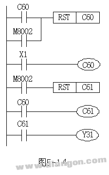
Expanding the range of counter values can be effectively achieved by connecting multiple counters in a cascading configuration. This method is particularly useful when you need to count large numbers that exceed the capacity of a single counter. In Figure 5-14, we see an example of how two counters can be connected in a cascade to achieve this expansion. In this setup, every time X1 is toggled on or off, C60 increments by one. After 50 such operations, the normally open contact of C60 closes, triggering C61 to count once. At the same time, another normally open contact of C60 resets C60 back to zero, allowing the process to start again. When C61 reaches 40 counts, it means that X1 has been toggled a total of 50 × 40 = 2000 times. At this point, the contact of C61 closes, which activates Y31. This demonstrates how the overall count value is determined by multiplying the individual counts of each counter in the cascade. This approach not only extends the counting range but also provides a flexible and scalable solution for various industrial automation applications. By using cascaded counters, engineers can design more efficient and accurate control systems without relying on a single high-capacity counter.

O.D114MM Hydraulic Dc Motors,O.D114MM Hydraulic Dc Motor,O.D114MM Dc Hydraulic Pump,O.D114MM Dc Hydraulic Pump Motor
Wuxi Jinle Automobile Motor Factory , https://www.wxjldj.com
