
UC3842/3843/3844/3845 These four chips are identified by using a 0-20V adjustable power supply to connect 384X VCC (7) and ground (5) to slowly increase the power supply voltage.
The 5V voltage of the 8-pin REF appears in a different order, and the 3843 and 3845 are 5VREF earlier than the 3842 and 3844. The specific 3843 and 3845 are around 10V, and the 3842 and 3844 are around 16V.
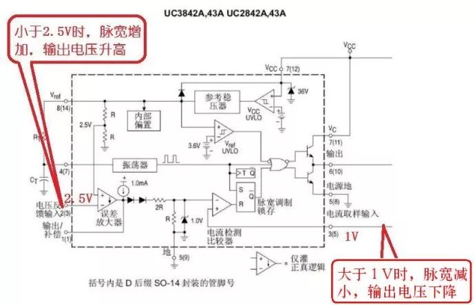
6 feet OUT foot. Because there is no feedback, the drive duty will output the maximum, so 3842, 3843 with a multimeter to measure the 6-pin voltage is about equal to VCC (duty cycle close to 100% multimeter test the effective value is Vcc voltage, you can also use the oscilloscope to test the duty cycle) When the 3844 and 3845 use a multimeter to measure the voltage, it is equal to half the voltage of VCC (the duty ratio is close to 50%, the multimeter tests the effective value as half of the Vcc voltage, and the oscilloscope can also be used to test the duty cycle).
In the switching power supply, the most commonly used integrated circuit model of the power supply PWM control circuit is UC3842 (or KA3842). The following briefly introduces the judgment method of UC3842:
In the original circuit, after replacing the damaged components, do not install the switch tube, and measure the voltage of the 7-pin of UC3842. If the voltage fluctuates between 10~17V, the other legs also have fluctuating voltages respectively, indicating the circuit. UC3842 is basically normal; if the voltage of pin 7 is low, the other pins have no voltage or do not fluctuate, then UC3842 is damaged.
Add a DC voltage of about +17V between pins 7 and 5 of UC3842. If the 8 pin has a stable 5V voltage and the 1, 2, 4, and 6 pins have different voltages, the UC3842 is basically normal, the operating current is small, and it is not easy to damage itself. The most common cause of damage is that after the power switch is shorted, a high voltage is applied from the G pole to its 6 pin, causing it to burn out. In some models, the G-grounded protection diode is omitted. When the power switch tube is damaged, the current limiting resistors of the UC3842 and G poles must be broken. Simply replace it at this time.
It should be noted that the source (S pole) of the power switch tube is usually connected to a small resistance high-power resistor as an overcurrent protection detection resistor. The resistance of this resistor is less than 1 ohm, and the load may not be loaded. (that is, the secondary voltage is low).
Since the working voltage and output power of UC3842 (KA3842) are far from UC3843 (KA3843), the 3842 series and 3843 series also have a big difference in starting voltage and closing voltage. The former has a starting voltage of 16V, and the voltage is turned off. It is 10V; the latter has a starting voltage of 8.5V and a shutdown voltage of 7.6V. These two series of ICs cannot be replaced directly. If it is necessary to replace the former with the latter, the circuit must be modified. Therefore, this must be paid attention to in the maintenance work.
Nickel Alkaline Battery,Solar Energy Battery,48V Nife Battery 200Ah ,Ni-Fe Battery 100~200Ah
Henan Xintaihang Power Source Co.,Ltd , https://www.taihangbattery.com