
1 Introduction
There are many electronic control units in the electric vehicle, small internal space and large environmental interference, which puts higher requirements on the control system and communication system. With its excellent operating characteristics, high reliability and unique design, CAN is especially suitable for communication between electronic control units of electric vehicles. In order to better conduct research in the laboratory, a well-functioning test and test platform was established to study the CAN bus system and its network protocol. First, DSP-based development designed the communication program for the motor controller node. Secondly, to understand the application requirements of CAN bus in electric vehicles, and design the application layer protocol of CAN bus. Finally, in order to verify the feasibility of the design agreement, the monitoring system of the electric vehicle was developed using VB6.0, and a database was established for the monitoring data to facilitate the management of data.
2 Motor controller node design
For the characteristics of electric motor controllers, TI's TMS320LF2407 chip is selected as the processor of the motor controller. Using a modular design concept, the communication program of the motor controller node is programmed to be easily ported to a DSP-based motor controller or other control unit. In the CAN bus system of electric vehicles, the real-time requirements of the motor controller are high, belonging to high-speed nodes, and the baud rate is set to 1 megabaud. The motor controller node mainly receives the control information of the motor working mode, SOC, vehicle speed, accelerator pedal position and brake pedal position uploaded by the bus, and simultaneously transmits real-time information such as working temperature, motor fault and working state of the motor. In this paper, the mailbox 2 of DSP2407 is used as the receiving mailbox, and the mailbox 5 is used as the sending mailbox, which is sent once every 20 milliseconds.
3 Electric vehicle monitoring system design
The electric vehicle CAN bus system is simulated in the laboratory, and the PC (with USB-CAN module) is used as the overall controller of the electric vehicle. Based on the operating mechanism and working principle of CAN-bus universal test software, the monitoring system of CAN bus technology based on PC is designed.
3.1 Overview of the monitoring system
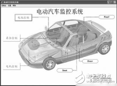
The monitoring system monitors the motor controller, battery controller and clutch controller via a console (PC with USB-CAN module). The main operation interface is shown in Figure 1. It can send and receive parameters in the CAN bus as needed to realize monitoring and control of each node of the bus. For example, motor parameters, including SOC, vehicle speed, fault level, operating mode, fault code, operating temperature, etc. The monitoring system also provides the ability to create nodes based on system expansion needs. In addition, data management functions are also available. During the execution of the monitoring system, the collected data is recorded in the Microsoft Access database, can be displayed in real time in tabular form, and can be opened by software Excel via the output button.
3.2 Monitoring System Communication Protocol
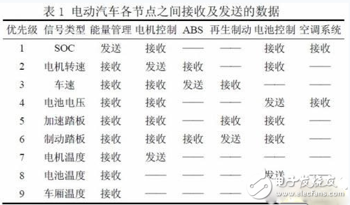
In the CAN protocol, only the data link layer and physical layer two-layer protocols are defined, and there is no specification for information processing. However, a complete network system cannot be separated from the application process of human-computer interaction, so the application layer protocol must be defined by the user. . According to the characteristics of electric vehicle operation, the communication protocol of the monitoring system is designed. In general, each electronic control unit (ECU) on an electric vehicle is divided into two categories: high speed and low speed nodes. Among them, the high-speed node includes a motor controller, an engine controller, a battery controller, an ABS/ASR control unit, and an energy management unit, and their ID codes are set to a higher priority. The low speed node includes an air conditioning system, an instrument display system, a lamp system, and the like. Table 1 shows the types of signals received and transmitted between the nodes of an electric vehicle. According to the data received and transmitted between the nodes of the electric vehicle, the types of information to be exchanged between the nodes, the parameters and the representation methods are specifically described. For example, the 8 bytes sent at the motor controller node are defined as: motor speed (double byte), motor torque (double byte), operating temperature (single byte), error level and code (single byte) The working mode (single byte) also has one byte as a spare. Table 1 shows the data received and sent between the nodes of the electric vehicle. For example, the 8 bytes sent at the motor controller node are defined as: motor speed (double byte), motor torque (double byte), operating temperature (single byte), error level and code (single byte) The working mode (single byte) also has one byte as a spare.
3.3 Monitoring system programming
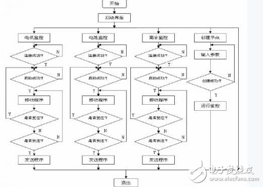
The monitoring system is to complete the monitoring of each node. According to the design requirements, the whole design can be divided into five design forms, including main form, motor controller monitoring form, battery controller monitoring form, clutch controller monitoring. Forms and create node forms and modular design. The node form can be created to easily create a monitoring window, set the node ID number and monitor variables. The monitoring system programming flow chart is shown in Figure 2.
4 Monitoring system testing
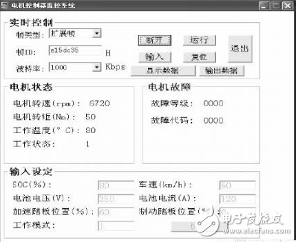
After completing the monitoring system programming of the PC, in order to verify whether the program works normally, and in order to verify the correctness of the designed DSP data acquisition and communication program of the lower computer. Here, the DSP data acquisition is combined with the communication program and the PC program for debugging. Set the baud rate of both to 1M baud. The test program of the DSP node includes A/D sampling (analog accelerator pedal position) and communication program. After the DSP runs, the data is collected and processed by the timer interrupt (20ms), and the signal is uploaded to the host computer (PC) through the CAN bus. On the other hand, the DSP automatically determines if there are instructions from the PC, such as battery voltage, battery current, accelerator pedal position, and operating mode. After receiving the data, the host computer processes it and hands it to the monitoring system for display. The test interface of the motor controller node is shown in Figure 3.
5 Conclusion
In order to meet the needs of electric vehicle monitoring, a CAN bus-based electric vehicle simulation test platform was set up, and a professional test instrument was equipped to form a CAN-BUS laboratory. The system has good scalability and can easily increase the electronic control unit (ECU) of the car that needs to be monitored. In addition, through the good connection between VB and ACCESS technology, data is saved in real time, which provides conditions for later data processing. In order to ensure that each message can be collected and processed by related nodes in time, the scheduling strategy of the message needs to be deeply studied to further optimize network management, especially network fault diagnosis and processing mechanism.
Siemens offers full standardized ready-to-use machine integration for OEM machine builders with full support by SIMATIC IT Line Monitoring System (LMS) for the line operating authority. To support this process, Siemens offers a concept based on PDI-Interface. The Plant Data Interface (PDI) based on the standards of OMAC User Group and Weihenstephan Standards.
Siemens Parts: Siemens MOORE, 6ES5 series, 6GK series, 6DD series, 6AR series.

Siemens Parts,Siemens Plc Parts,Siemens Spare Parts,Siemens Electrical Parts
Xiamen The Anaswers Trade Co,.LTD , https://www.answersplc.com