
The quadrotor is an unmanned aerial vehicle with six degrees of freedom and four control inputs for vertical takeoff, landing, forward flight, side flight and reverse flight. Four rotors can cancel the reverse torque. A special anti-torque paddle is required. It is widely used in areas such as unmanned reconnaissance, forest fire prevention, disaster monitoring, and urban patrols. The flight control system is the core part of the quadrotor, and its performance determines the performance of the entire system. In recent years, the autonomous flight control of micro-miniature quadrotor UAVs has received extensive attention from researchers. With the development of computer technology and electronic technology, the research and development of small aircrafts in China has gradually warmed up, and many companies have formed industries. For example, Dajiang Company has commercialized multi-axis aircraft such as quadcopters. The main focus of domestic research is three aspects: attitude control, sensor technology development, application of new materials, and research in the field of batteries. Typical representatives include Harbin Institute of Technology, Beijing University of Aeronautics and Astronautics, Nanjing University of Aeronautics and Astronautics, and National University of Defense Technology. Advanced PID control is widely used in control algorithms.
In this paper, the STM32C8T6 with ARM Cortex-M3 architecture is used as the aircraft control processor, and the MPU-6050 is used as the attitude sensor of the aircraft. The low-power 2.4GHz nRF24L01 is used as the wireless transmission device, and the HC-RS04 ultrasonic is used as the obstacle alarm sensor design system. Hardware circuit. After experimental debugging, the hardware system can run stably and reliably.
1 system overall structural design
1.1 Physical structure design
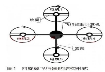
The quadrotor consists of a cross bracket and four propellers. The flight control processor and external equipment are placed in the middle of the bracket. The four propellers have the same radius and angle, and are arranged symmetrically in the left, right, front and rear directions. The four motors are symmetrically mounted on the bracket end, wherein the motor 1 and the motor 3 rotate counterclockwise, and the motor 2 and the motor 4 rotate clockwise, and the running state of the motor is controlled by changing the rotational speed of the four motors. Its structural form is shown in Figure 1.
1.2 Working principle
When the four-rotor aircraft is working, the speed of the four motors is adjusted by the motor speed control system to realize different changes of the lift, thereby controlling the running state of the aircraft. The motor 1 and the motor 3 of the aircraft rotate counterclockwise, and the motor 2 and the motor 4 rotate clockwise. At this time, the gyro effect and the air torque effect of the aircraft are cancelled, thereby ensuring that the aircraft can balance the stable flight. The flight state of the aircraft is controlled by appropriately changing the rotational speed of the motor.
1.3 Overall system design of aircraft control system
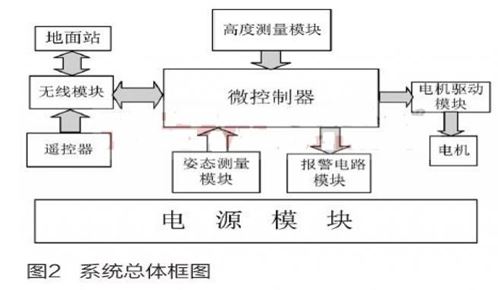
The flight control system is divided into two parts, the ground and the airborne, which are physically separate from each other and logically connected to each other. The ground section is further divided into a ground station section and a remote control section, which are independent of each other. The entire flight control system consists of a microcontroller module, a wireless module, a motor drive module, an attitude measurement module, a height measurement module, an alarm circuit module, a ground station, and a remote controller. The overall block diagram of the system is shown in Figure 2.
2 system main function module hardware circuit design
2.1 Microcontroller Module
The control system is a multi-input multi-output system. The main input signal of the control module has the measurement data of each sensor, and the output signal is a four-way variable pulse width motor control signal, which requires multiple timing/counter control signal pulse widths. The system needs to process the data from many sensors and needs to send the data back to the ground system. It needs real-time control and the response speed must be fast. In addition, the interface of the sensor of this system is diversified, and more kinds of interfaces are needed to facilitate software reading. Based on these requirements, the aircraft microprocessor module in this design uses the ARM Cortex-M3 core STM32F103C8T6, its clock frequency can reach 72MHz, and has IIC bus interface, JTAG interface, SPI interface, AD acquisition interface, multi-channel PWM output and Multiple serial ports for easy loading and debugging of various sensors. This microcontroller has eight timers that are satisfied for both signal acquisition and PWM output.
2.2 Attitude measurement module
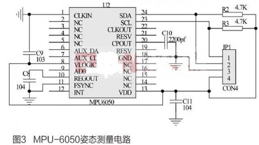
Four-rotor aircraft are greatly affected by motor vibration and external disturbances. It is difficult to establish accurate mathematical models, and its load is limited. Generally, inertial devices are used as attitude measuring devices. Attitude measuring components are an important part of the whole hardware system. This design takes into account the hardware design principles and uses the MPU-6050 as the attitude sensor for the aircraft. The MPU-6050 communicates through the IIC protocol interface. It only needs to connect the SDA data line and SCL clock line of the MPU-6050 to the STM32 general-purpose I/O port. The circuit is shown in Figure 3. In order to stabilize the output and avoid the open bus open drain, R2 and R3 are used as pull-up resistors of SDA and SCL to improve the load capacity of the bus. In the circuit, C9 is a digital power supply voltage filter capacitor, C8 is a calibration filter capacitor, C10 is a charge pump capacitor, and C11 is a power supply voltage filter capacitor.
2.3 Wireless Communication Module
The system requires wireless communication in these three aspects: first, the signal of the remote controller needs to be sent out through the wireless module. Second, the ground station needs to receive the attitude data of the flight controller and need to send control parameters. Finally, it is necessary to receive data from the remote control and the ground station at the flight controller. In combination with communication distance, cost and other factors, this design uses nRF24L01 wireless module device. The transmitting circuit can be constituted by an LC oscillating circuit. In order to facilitate maintenance, the wireless module is separated by an interface.
2.3.1 Remote Control Module
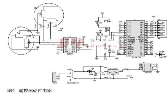
This design adopts the joystick control mode, which uses the digital-to-analog converter to convert the analog quantity of the joystick into a digital quantity, and then transmits the converted digital signal to the small controller. After a certain data processing, it is transmitted through the wireless for the purpose. The aircraft controller receives the utilization. The nRF24L01 is used as the wireless transmitting device of the remote controller. In order to facilitate the digital-to-analog conversion, the remote control rocker uses the rocker potentiometer to measure the stroke amount of the remote control by collecting the voltage value of the potentiometer; since the remote controller processes the signal single, it is not required. The high-speed processor uses an 8-bit 51 single-chip STC89C52RC as the controller of the remote controller to collect the analog signal of the joystick and send the collected data. PCF8591 is used as the data acquisition device, which contains 4 analog inputs and 1 analog output. It is a standard IIC communication and can meet the design requirements. The remote control hardware circuit is shown in Figure 4.
2.3.2 Ground station module
The aircraft ground station mainly performs the following two functions: (1) detecting the flight state of the aircraft when the aircraft is stably flying, transmitting control parameters to the aircraft to operate according to the control algorithm; and (2) completing the aircraft PID during the aircraft commissioning phase. Modification and adjustment of parameters. Since the PC is generally left to the user to operate the USB interface, the nRF24L01 communication interface is the SPI interface. This design selects 51 single-chip microcomputer to read the data of nRF24L01, and continues to communicate with the PC through the USB to serial port chip by the single-chip microcomputer to complete the ground. Station data transmission function.
2.4 Motor drive module
2.4.1 Motor drive principle
This design uses a DC brushless motor as the power drive device for the aircraft. According to the commutation principle of brushless DC motor, the control form of brushless DC motor is divided into: open loop control, speed negative feedback control and voltage feedback plus current positive feedback control. Among them, the open loop control has no feedback for proofreading, and is applied to places where the speed accuracy is not high; the mechanical performance of the speed negative feedback control is good; the voltage feedback plus current positive feedback control is generally applied in the occasions with high dynamic performance requirements. For this design, it is necessary to adjust the motor speed in real time, and the speed regulation frequency is relatively large, so the voltage feedback plus current positive feedback control method is adopted in this design.
2.4.2 Motor drive circuit design
According to the motor control principle, this design divides the motor drive circuit into three parts: microprocessor, back EMF detection and power drive.
(1) microprocessor
Since the commutation frequency of the brushless DC motor is relatively high, it is not appropriate to use a low-frequency processor, and the rotation of the motor generates a rotating magnetic field, which greatly interferes with the processor. By comparison, this design uses ATMEGA8 microcontroller as the motor drive microprocessor.
(2) Back EMF detection
In the process of commutation, it is necessary to continuously detect the position of the rotor, and the position information of the rotor can be known by the counter electromotive force generated by the rotor. By the principle of partial pressure decay, the voltage of the opposite electromotive voltage of the motor relative to the neutral point is detected, thereby Determine the position of the rotor. The back electromotive force detection circuit is shown in Figure 5.
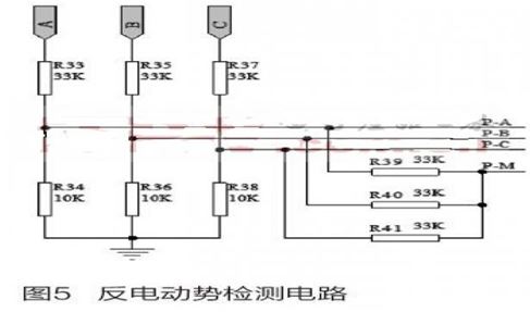
Among them, A, B, C terminals are motor three-phase voltage, R33~R38 are voltage dividing resistors, PA, PB, PC respectively have three opposite electromotive force corresponding voltages, and PM is neutral point voltage.
(3) Power drive
The power drive is to provide a large current to the motor to achieve stable operation. This design uses a parallel MOS tube to increase the output current. In each phase, the bridge arm is connected in parallel with three P-channel MOS tubes to reach the three-phase. For the purpose of full bridge control, three N-channel MOS transistors are also connected in parallel on the lower arm of each phase.
3 hardware system debugging
3.1 PWM control aircraft drive motor debugging
By energizing four motors and adding different duty cycle PWM waveforms to control the motor speed, record the change of power supply voltage and current, and stabilize the output 11.1V, different duty cycle, power supply current change As shown in Table 1.
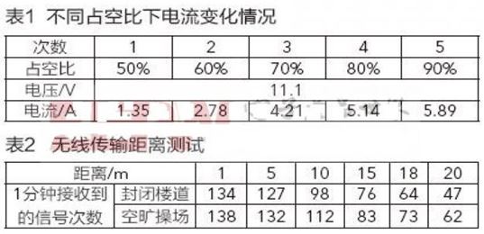
It can be seen from Table 1 that the larger the duty cycle is, the larger the current required for the motor drive operation is. When the duty ratio reaches the limit value, the current output changes little. Experiments show that the hardware system can operate reliably.
3.2 Wireless communication debugging
The performance characteristics of the wireless module are determined by testing the wireless connectivity, transmission distance, and packet loss rate. Set the remote control to the transmission mode, set the ground station to the receiving mode, use the warning light of the ground station to indicate the status of the reception, successfully accept a flash, and change the distance between the remote control and the receiver to record the indication within one minute. The number of flashes of the lights is used to evaluate the quality of the wireless transmission; the tests are carried out in the teaching building corridor and the open playground respectively. The detailed records are shown in Table 2.
It can be seen from Table 2 that the transmission effect of wireless communication after 15m is significantly reduced, which is determined by the power of the wireless communication module. Experiments show that the wireless communication part can operate reliably within the design requirements.
3.3 Comprehensive debugging
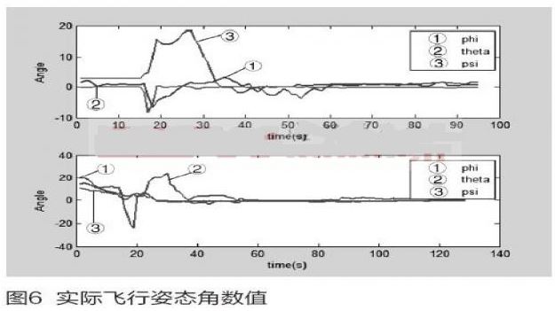
Figure 6 is a plot of the attitude of the PID control algorithm downloaded to the quadrotor aircraft controller for actual flight control, where 1 represents the roll angle, 2 represents the pitch angle, and 3 represents the yaw angle. Figure 6 is the angle data of the attitude re-convergence to the stationary (0,0,0) state after the aircraft is subjected to crosswind interference. The figure below shows the angle data from the controlled convergence of the aircraft to the steady (0,0,0) state. It can be seen from the experimental results that the system can operate stably.
4 Conclusion
The design of the control system of the four-rotor aircraft and the hardware component selection and circuit design of each module of the system were completed. The system hardware circuit was debugged. The experimental results show that the system can operate stably and reliably.
Uni Directional Mic,Uni Directional Microphone,Uni Directional Dynamic Microphone,Uni Directional Condenser Microphone
NINGBO SANCO ELECTRONICS CO., LTD. , https://www.sancobuzzer.com