**Abstract:**
Aiming to solve the limitations of traditional ultrasonic power supplies in driving and locking different resonant frequency segments, this paper presents an FPGA-based system for automatic frequency search, tracking, and dynamic matching in a wide frequency domain. The system is designed to handle resonant transducers with varying frequencies by adapting its output frequency in real time. Based on the impedance characteristics of the transducer, a dynamic step-size frequency search algorithm is implemented to quickly locate the resonant frequency. Additionally, the system adjusts the output frequency using the phase difference between voltage and current feedback to achieve phase locking. Experimental results demonstrate that the proposed system offers fast frequency search, accurate tracking, and strong adaptability to various transducers.
**0 Introduction**
Ultrasonic welding, cleaning, and inspection technologies have promising applications [1]. However, challenges such as resonance frequency drift and lag in tracking remain unresolved. Most existing ultrasonic devices consist of a power supply and a transducer, but a single power supply cannot effectively drive or lock transducers with different resonant frequencies, limiting its performance in wide frequency domains [2]. Therefore, developing a broadband ultrasonic power supply capable of automatic frequency tracking and dynamic matching of different transducers has significant practical value [3].
This paper introduces a wide-frequency-domain ultrasonic power supply system based on the XILINX ZYNQ series FPGA (XC7Z0201CLG484I). The system operates in the 20–40 kHz range and can drive various transducers within this band, making it highly adaptable for different applications.

**1 Ultrasonic Power System**
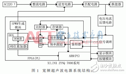
The ultrasonic power supply consists of a rectifier circuit, inverter circuit, matching circuit, feedback circuit, and main control circuit. The system block diagram is shown in Figure 1. The FPGA integrates a dual-core ARM Cortex-A9 processor (PS) and programmable logic (PL). The PL handles tasks like frequency search, tracking, phase discrimination, SPWM generation, and DDS. The PS manages interface display and parameter processing. The matching circuit includes a high-frequency transformer and an improved T-network, which helps match the load to a purely resistive state, improving efficiency.
DDS generates sine waves using a phase accumulator and a sine wave lookup table. The frequency control word determines the output frequency, calculated as:
$$ f_{out} = \frac{F_{word} \cdot f_{clk}}{2^N} $$
where $ N $ is the phase accumulator bit length, $ f_{clk} $ is the system clock, and $ F_{word} $ is the frequency control word. The DDS signal modulates a triangular carrier from the SPWM module to generate a PWM wave, adjusting the inverter’s output frequency accordingly.
After power-on, the system first searches for the transducer’s resonant frequency by analyzing the feedback current. It records the maximum current at resonance and then tracks the frequency by aligning the voltage and current phase. If the system detects a mismatch due to a new transducer or sudden load change, it restarts the frequency search.
**2 Frequency Search**
When the output frequency matches the transducer’s resonant frequency, the system achieves maximum efficiency and stability [6]. Experiments show that the current through the load is highest at resonance [7-8], so the frequency search is based on current detection.
Figure 2 shows the impedance curve of a transducer with resonant frequencies at 22 kHz and 32.32 kHz. Near resonance, the impedance changes significantly, causing large current variations. Far from resonance, the impedance change is minimal. Based on this, a frequency search method using current maximum is implemented on the FPGA platform.
The frequency search process starts at 20 kHz. The system compares the current feedback with the previous cycle. If the difference is below a threshold, it increases the frequency step size; if above, it reduces the step size. Once the maximum current is found, the system records the corresponding frequency.
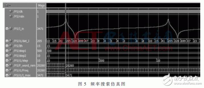
Figure 3 illustrates the FPGA implementation of the frequency search, while Figure 4 shows the software flowchart. Key variables include: Freq (search range), F_word_rem (resonant frequency control word), I_in (input current), I_max (maximum current), step1/step2 (large/small steps), Ith (threshold), and det_I (current difference).
After initialization, the system continuously checks the current and adjusts the frequency step size accordingly. When the frequency approaches resonance, it uses small steps to precisely locate the peak. Once the search is complete, the system locks onto the resonant frequency.
Figure 5 shows a ModelSim simulation of the frequency search. The cursor indicates the maximum current point, which corresponds to the resonant frequency. The system uses a variable step size, switching to smaller steps near resonance for accuracy.

Fiber Optic Components,Parts Of Fiber Optic Cable,Fibre Optic Connector,Parts Of Optical Fiber
Cixi Dani Plastic Products Co.,Ltd , https://www.danifiberoptic.com
