
In this paper, the generation mechanism of switching power supply EMI is analyzed in detail, and a series of EMI suppression strategies are proposed to effectively improve the electromagnetic compatibility of switching power supplies.
The switching power supply is a power electronic product that uses power semiconductor devices and integrates power conversion technology, electronic electromagnetic technology, and automatic control technology. Because of its advantages of low power consumption, high efficiency, small size, light weight, stable operation, safe and reliable, and wide voltage regulation range, it is widely used in computers, communications, electronic instruments, industrial automation, national defense and household appliances. field. However, the switching power supply has poor transient response and is prone to electromagnetic interference (EMD, and the EMI signal occupies a wide frequency range and has a certain amplitude. These EMI signals pollute the electromagnetic environment through conduction and radiation, to communication equipment and electronic instruments. This causes interference and thus limits the use of switching power supplies to some extent.
1 Causes of electromagnetic interference from switching power supplies
Electromagnetic interference (EMI) is a performance impairment caused by an unexpected electromagnetic disturbance in an electronic system or sub-system. It consists of three basic elements: the source of interference, that is, the device that generates electromagnetic interference energy; the way of combining, that is, the path or medium that transmits electromagnetic interference; the sensitive device, that is, the device, device, subsystem or device that is damaged by electromagnetic interference or system. Based on this, the basic measures for controlling electromagnetic interference are: suppressing the source of interference, cutting off the path of mismatch, and reducing the response of sensitive equipment to interference or increasing the level of electromagnetic sensitivity.
According to the working principle of the switching power supply, the switching power supply first rectifies the commercial frequency alternating current into direct current, and then inverts into high frequency alternating current, and finally rectifies and filters the output to obtain a stable direct current voltage. In the circuit, the power transistor and the diode mainly work in the state of the switch tube, and work in the microsecond order; during the turn-on and turn-off process of the triode and the diode, the current changes greatly during the rising and falling time, and the RF energy is easily generated. Source of interference. At the same time, potential electromagnetic interference is also formed due to the leakage inductance of the transformer and the spike caused by the reverse recovery current of the output diode.
Switching power supplies typically operate at high frequencies with frequencies above 02 kHz, so their distributed capacitance is not negligible. On the one hand, the insulating sheet between the heat sink and the collector of the switch tube has a large contact area and a thin insulating sheet. Therefore, the distributed capacitance between the two cannot be ignored at high frequencies, and the high-frequency current flows through the distributed capacitor. On the heat sink, it flows to the chassis ground to generate common mode interference. On the other hand, there is a distributed capacitance between the primary and secondary of the pulse transformer, which can directly confuse the primary winding voltage to the secondary winding. Common mode interference occurs on the two power lines that make DC output.
Therefore, the interference sources in the switching power supply are mainly concentrated in voltage and current variations, such as switching tubes, diodes, high-frequency transformers and other components, as well as AC input and rectifier output circuit parts.
2 Measures to suppress electromagnetic interference of switching power supply
Generally, switching power supply EMI control mainly uses filtering technology, shielding technology, sealing technology, grounding technology, and the like. EMI interference is divided into conducted interference and radiated interference according to the propagation route. The switching power supply is mainly conducted interference, and the wide frequency range is about 10 kHz to 30 MHz. The countermeasures for suppressing conducted interference are basically solved in three frequency bands of 10 kHz to 150 kHz, 150 kHz to 10 MHz, and 10 MHz or more. The main interference is mainly in the range of 10 kHz to 150 kHz, and is generally solved by a general-purpose LC filter. The common mode interference is mainly in the range of 150 kHz to 10 MHz, and is usually solved by a common mode rejection filter. The countermeasures for the frequency band above 10 MHz are to improve the shape of the filter and to take electromagnetic shielding measures.
2.1 Using AC input EMI filter
There are usually two ways in which the interference current is transmitted on the wire: the common mode and the differential mode. Common mode interference is the interference between the carrier fluid and the earth: the interference size and direction are the same, and exist in any relative ground of the power supply, or between the neutral line and the earth, mainly generated by du/dt, and the di/dt also produces a certain total. Mode interference. The differential mode interference is the interference between the carrier fluids: the interference is equal in magnitude and opposite in direction, and exists between the power phase line and the neutral line and between the phase line and the phase line. When the interference current is transmitted on the wire, it can be either common mode or differential mode; however, the common mode interference current can only interfere with the useful signal after it becomes the differential mode interference current.
The above two types of interference exist on the AC power input line, usually low-band differential mode interference and high-band common mode interference. Under normal circumstances, the differential mode interference amplitude is small, the frequency is low, and the interference caused is small; the common mode interference amplitude is large, the frequency is high, and the radiation can be generated by the wire, and the interference caused is large. If an appropriate EMI filter is used at the input end of the AC power source, electromagnetic interference can be effectively suppressed. The basic principle of the power line EMI filter is shown in Figure 1. The differential mode capacitors C1 and C2 are used to short-circuit the differential mode interference current, while the intermediate connection grounding capacitors C3 and C4 are used to short-circuit the common mode interference current. The common mode choke is composed of two coils that are equal in thickness and wound in the same direction on a magnetic core. If the magnetic coupling between the two coils is very tight, the leakage inductance will be small and the difference will be within the power line frequency range.
The mode reactance will become very small; when the load current flows through the common mode choke, the magnetic lines of force generated by the coils connected in series on the phase line are opposite to the lines of magnetic force generated by the coils connected in series on the center line, and they are in the core. Cancel each other out. Therefore, even in the case of a large load current, the core does not saturate. For the common mode interference current, the magnetic fields generated by the two coils are in the same direction, which will exhibit a large inductance, thereby attenuating the common mode interference signal. Here, the common mode choke coil is made of a ferrite magnetic material having a high magnetic permeability and a good frequency characteristic.
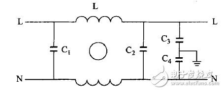
Figure 1 Basic circuit diagram of power line filter
2.2 Using the absorption loop to improve the switching waveform
During the turn-on and turn-off of the switch or diode, due to the transformer leakage inductance and line inductance, the diode storage capacitor and distributed capacitance, it is easy to generate a spike voltage at the collector, emitter and diode of the switch. The RC/RCD absorption loop is usually used, and the RCD surge voltage absorption loop is shown in Figure 2.
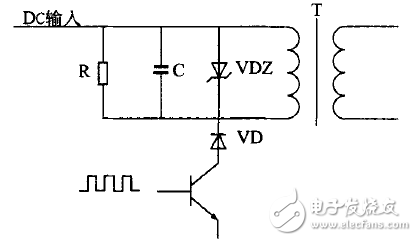
Figure 2 RCD surge voltage absorption loop
When the voltage on the absorption loop exceeds a certain range, the devices are quickly turned on, thereby venting the surge energy and limiting the surge voltage to a certain amplitude. The saturable core coil or the microcrystalline magnetic bead is connected in series on the positive electrode lead of the collector of the switch tube and the output diode, and the material is generally cobalt (Co). When the normal current is passed, the core is saturated, and the inductance is small. Once the current flows in the opposite direction, it will generate a large back EMF, which effectively suppresses the reverse surge current of the diode VD.
Full Spectrum Led Grow Light For Greenhouse/Hydroponics/Plants Growing
What is Full spectrum led chip ?
It is the newest trend for LED Horticulture Lighting. Advanced Led Grow Lights chip, not provide sigle color,provide broad spectrum 400nm~840nm ,simialr with sun light ,but most is red and blue ,it is best for Led Horticulture Grow Lights.This is a revolutionary step for LED Grow Lights which have previously been unable to act as the sole light source for the indoor garden.Suitable for all stages of plant growth.
How to Select the Best Grow Light for your Greenhouse?
The plant needs light to thrive cause the light is essental for photosynthesis.without it,plants can not make food.but light can also be too intense,too hot or last too long for growing healthy plants.plant growth accelerates with abundant light because more of the plant`s leaves have exposure,which means more photosynthesis.in the winter,days are not long enough,but many plants still need 12 hours or more of light per day.now,adding led grow lights to your greenhouse is an nice choice if you live in the north, and can not get enough daylight in winter.you might be take HID into consideration,cause it has high output and cover a wide area.but now,we providing you some dfferent.the newest type of grow lights use LED technology.
Provides Maximum Light Density and optimizing spectrum(410nm-740nm,white)
As we know that the plants need more light from the blue side of the spectrum during their seedling stage and when developing foliage and require light from the orange to red side of the spectrum while inblooming and fruiting phases. We adopting lastest intergrated COB technology, white , more red and blue PAR(410-740nm) per Watt than any other lighting fixture for the best color uniformity.
Dual Veg and Bloom for plant growth and bloom
The Led grow lights feature selectable VEG and BLOOM light spectrums to deliver maximum performance from seeding through the flower stage and finally harvest.
Increase yields and potency
Using high quality lense that hyper-focus the lights on your canopy.the photons are beamed directly to the plants.this gives growers the ability to get greatest possible crop yield.
Reduce your costs with energy efficiency
Energy-efficient cannabis grow lights cost between 40%-60% less to operate compared to HID lam year
Led Grow Light also eliminate the needs for ballasts and reflectors while they minimize the cooling systems,accelerating your payback.you will see the electrical bills trimmed by approximately half,year after year.
Installs and operates simply
the input voltage is AC100V-240V,fit for the world standard,built-in power supply.do not need other equipment,just access to the Plug,the lamp will be work smoothly. The Led Grow Lighting is small size,just few inches and easy to install.it is the good option for some greenhouse.
Long lifespan
Using built-in quiet fans and the shutter in the wind,induced draftfrom all sides.runs with quiet. Useadvanced isolation power supply and soft start protection technology, to prevent the high voltage when turn on the light from damagingthe lamp body.
Philizon LED lights have the HIGHEST PAR/LUMEN OUTPUT PER WATT of any LED grow lights! 2x-3x the intensity of any other lights!
SUPERIOR 12-band full spectrum from the depths of UV to the heights of IR - The most complete and efficient spectral output available
Selectable VEG/FLOWER switches with 8x high speed whisper quiet fans plus ALL NEW upgraded aluminum cooling heat sinks
1600w HPS replacement with 8.5ft x 7.5ft coverage at 3.28feet height PERFECT for massive commercial applications or using multiple units for even coverage.COMPLETE 3 YEAR WARRANTY plus our exclusive 90 DAY SATISFACTION OR RETURN GUARANTEE
Application
Greenhouse, Hydroponics, Aeroponics, Home Garden, Farm, Vegetable Shed, Botanic Garden, Flower Exhibitions, Horticulture, Hydroponics, Hemp Cultivations , Medical Plants Cultivations, etc.
Warranty
1.3years Manufacturer's Warranty for defective items within 3 years
2.We will guide you to fix it if gets small problems within 3 years
3.We will send you new items if the products are totally broken since technical or quality matters within 3 years
4.Retun and Refund: we provide 30days no question item return, we will refund all your money after we get the item, and we both provide 50% of the return shipping fee.
Led Horticulture Grow Lights,Full Spectrum Indoor Grow Lights,Indoor Grow Lights,Led Grow Lamps
Shenzhen Phlizon Technology Co.,Ltd. , https://www.philizon.com