
Last time, I briefly introduced the role of DDR3 ODT. Today, I will talk about several ODT operation modes in detail. The first is the ODT synchronization operation mode, which is also the most used and most commonly used mode.
As long as the DLL is open and locked, it is in synchronous ODT mode. When the DLL is closed, the Direct ODT (Direct ODT) function cannot be used. At this time, you must continue to set the ODT pin low and set the RTT_Nom resistance value to 0 (set MR1{A9,A6,A2} to {0,0,0} ).
In synchronous ODT mode, RTT will be turned on ODTLon clock cycles after the rising edge of the clock where ODT is sampled high, and at the same time, RTT will be registered after ODT is low (sampled and registered) ODTLoff clock cycles are turned off. Among them, the latency of ODT depends on the write latency (WL): ODTLon=WL-2; ODTLoff=WL-2;
Supplementary note: WL, the write latency period, that is, the latency period from the write command to the first data input (write from the host to the DDR). WL=AL+CWL.
The following table:
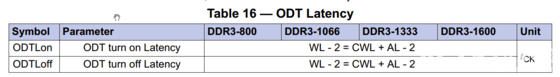
In synchronous ODT, we mainly focus on the following four parameters:
ODTLon, ODTLoff, tAON,min,max, tAOF,min,max.
ODTLon, ODTLoff have already been introduced, let's talk about tAON, min, max, tAOF, min, max.
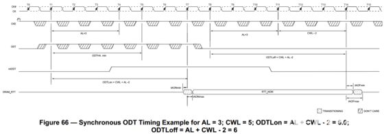
Minimum RTT turn-on time (tAONmin) is the point in time when the device leaves high impedance and ODT resistance begins to turn on. Maximum RTT turn-on time (tAONmax) is the point in time when the ODT resistance is fully on. Both are measured from ODTLon.
Minimum RTT turn-off time (tAOFmin) is the point in time when the device starts to turn off the ODTresistance. Maximum RTT turn off time (tAOFmax) is the point in time when the on-die termination hasreached high impedance. Both are measured from ODTLoff.
When ODT is asserted, it must remain high until ODTH4 is satisfied. If a Write command is registered by the SDRAM with ODT high, then ODT must remain high until ODTH4 (BL = 4) or ODTH8 (BL = 8) after the Write command ( see Figure 67). ODTH4 and ODTH8 are measured from ODT registered high to ODT registered low or from the registration of a Write command until ODT is registered low.
Two examples of ODT operations:

Note: The examples given above are examples of writing and do not apply to reading mode. As DDR3 SDRAM does not support simultaneous read and write (As the DDR3 SDRAM can not terminate and drive at the same time), RTT must be set to low power by setting the ODT pin half a clock cycle before data reading RTT is prohibited.
Important note: In other words, the ODT function in DDR3 SDRAM only supports write operations, not read operations. In other words, when reading data, you need to turn on the ODT of the main control terminal (provided that the host supports ODT) and turn off the ODT of the DDR3 terminal; when writing data, the opposite is true; when the data line is idle, turn off the ODT at both ends.
Fiber optic splitter is also called optical splitter, is one of the most important passive devices in optical fiber link, is with multiple inputs and multiple output end of the optical fiber connected devices. The fiber optic splitter by the light splitting principle can be divided into the fused biconical taper (FBT type) and planar waveguide type (PLC type).
We provide the whole series of 1xN and 2xN splitter products that are tailored for specific applications. Fiber Optic Splitter Plc, Fiber Optic Cable Splitter, Optical Splitter, Mini Type Plc Splitter, Cassette Type PLC Splitter, Insertion Module Plc are available.


Steel Tube PLC Splitter,Plc Splitter Steel Tube,Tube Type Fiber Optic Splitter,Fiber Optic Plc
Sijee Optical Communication Technology Co.,Ltd , https://www.sijee-optical.com