
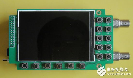
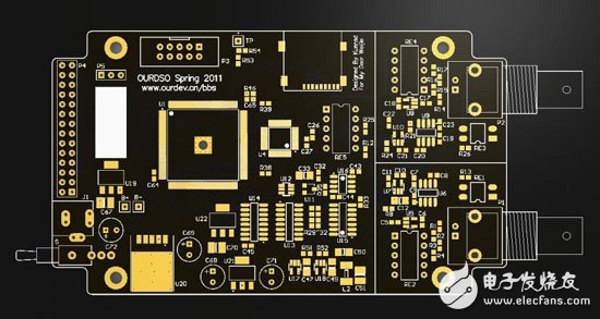
This version of the PCB is designed according to a commercially available universal housing, that is, there is a "shell". If you can use Amo's machine to open the hole, then solve a lot of headaches!
Originally this version of the oscilloscope is using the PSP LCD screen, the test found that the power consumption is larger than the 3.5 inch used now, in fact, the resolution of this screen is slightly higher than the PSP 480 * 272, the reality is more delicate, just No 4.3-inch screen looks cool.
First put the download address of the schematic, PCB and program files:
Homemade dual channel digital oscilloscope schematic
Homemade dual channel digital oscilloscope PCB
Homemade dual channel digital oscilloscope program
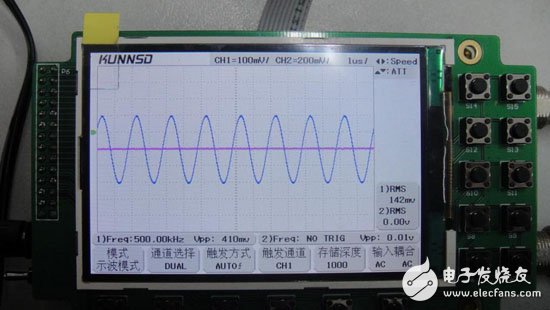
Probably the performance parameters are as follows:
Number of channels: 2 channels
Analog bandwidth: 30MHz
Sample rate: dual channel, every 125Msps
Vertical accuracy: 8bit
Memory depth: no less than 8KB per channel
Voltage sensitivity: 10mv/div~5v/div (1:1 probe)
Sweep range: 100ns/div~5s/div
FFT function: 1024 point FFT
XY function
Trigger mode: single, normal, automatic, adjustable trigger voltage with advanced trigger function
480*320/3.5 inch high resolution LCD display.
Operating voltage: 6.2V~9V, 8V regulated power supply is recommended
Maximum current consumption: 350mA (8V), because the digital part uses DC/DC regulator circuit, so the current consumption has a certain relationship with the supply voltage.
Key Function:
S0: mode selection (select oscilloscope and FFT)
S1: channel selection (channel 1, channel 2, dual channel and XY mode ie Lisa Yutu)
S2: Trigger mode selection (automatic rising edge, automatic falling edge, normal rising edge, normal falling edge)
S3: Trigger channel selection (trigger channel defaults to current channel in single channel, cannot be selected, only available in dual channel and XY mode)
S4: Storage depth selection (1000 points, 2000 points, 4000 points, 8000 points per channel selection) Note: The use of ground storage depth at low sweep speeds can achieve better real-time performance.
S5: Input coupling selection (AC coupling AC and DC coupling DC, respectively)
S6: Up and down key function selection (set the function of the up and down keys, respectively sensitivity ATT, baseline position Level, trigger level TrigY) Note: s12 and s10 are the up and down keys of 1 channel, s13 and s11 are the up and down keys of 2 channels
S7: Left and right button function selection (set the function of left and right button, set TrigX for sweep speed control and trigger horizontal position respectively) Note: s14 and s15 are left and right buttons
S8: Single trigger (single trigger function, only the trigger mode can be used under normal conditions, not available in automatic mode)
S9: Run stop button
Din Rail With Ups,New Design Din Rai ,35/15 Din Rai,Din Rai Switching Power
Wonke Electric CO.,Ltd. , https://www.wkdq-electric.com