
Basic principle of polarizing film for liquid crystal display
The basic principle of polarized light and polarized film Most people are still unfamiliar with the term polarized film and not very clear. Therefore, the phenomenon and basic principle of polarized light will be explained here.
Polarized light Human understanding of light can be divided into the following four important stages in order:
1. In the seventeenth century, Newton first began to do systematic research on light. He discovered that the so-called white light (White Light) is composed of all colored lights (Colored Light). To explain this phenomenon, many different theories have been derived.
2. At the beginning of the 19th century, Thomas Young used wave theory to successfully explain most of the optical phenomena such as reflection, refraction, and diffraction.
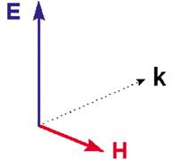
In 3.1873, Maxwell discovered that the light wave is an electromagnetic wave, in which the electric and magnetic waves are interdependent and cannot be separated, and the electric field (E), the magnetic field (H) and the direction of the electromagnetic wave (k) are perpendicular to each other relationship.
figure 2
4. At the beginning of the twentieth century, Einstein discovered that the energy of light can only be explained by the particle theory, thus deriving quantum theory. In other words, light has both wave and particle characteristics.
Because the theory of polarized light is explained by wave theory, all previous discussions have considered light as an electromagnetic wave, and in order to simplify and understand, we only consider the electric field vector E. The E of non-polarized light can be represented by Figure 2. Many symmetrical equal-length radiation lines in Figure 2 indicate that E vibrates on the plane composed of E and H, and the chances of vibrating in all directions are equal. When the distribution of E is uneven, it is called polarized polarization (PolarizaTIon), as shown in Figure 3 is partially polarized light, when E only vibrates in one direction is called linear polarized light (Figure 4). From a vector point of view, when the vectors in each direction in Fig. 2 are projected onto two mutually perpendicular coordinate axes, X and Y, unpolarized light can be decomposed into two linear polarized lights that are perpendicular (Fig. 5).
Figure 2: Non-polarized aurora
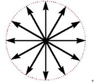
Figure 3: Partially polarized light
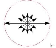
Figure 4: Linear polarized light

Figure 5: Linear polarized lights perpendicular to each other 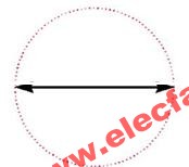
Manufacturing of polarized light Generally speaking, the method of manufacturing polarized light consists of the following three steps:
1. Manufacture ordinary non-polarized light (Figure 2).
2. Decompose this non-polarized light into two linear polarized lights that are perpendicular to each other (Figure 5).
3. Abandon one polarized light and apply another polarized light (Figure 4).
An instrument that can decompose unpolarized light into two polarized lights is called a polarizer. Polarizers can generate polarized light by using optical effects such as absorption, reflection, refraction, and diffraction.
There are several types of commonly used polarizers:
(1) Reflective type When light enters the glass surface obliquely, the reflected light will be partially polarized. The continuous reflection effect of the multilayer glass can be used to convert non-polarized light into linear polarized light.
(2) The complex refracted type joins two calcite crystals, and the incident light will be decomposed into two polarized lights, called ordinary light and extraordinary light.
(3) The dichroic microcrystal type regularly arranges dichroic fine crystals on a transparent sheet, which is the first artificially made polarizing film.
(4) The polymer dichroic type uses a light-transmissive polymer film to orient the molecules in the film, and then adsorbs the dichroic substance. This is the most important method for producing polarizing films. Such absorption polarizers exist in the form of films or plates or plates, so they are also commonly referred to as polarizing films or polarizing plates or sheets. Another more popular name in English is Polarizing Filter.
The origin of polarizing film Polarizing film was invented by Polaris founder Edwin H. Land in 1938. Today, sixty years later, although the polarizing film has many improvements in production techniques and equipment, the basic principles and materials used in the process are still the same as they were sixty years ago. Therefore, before explaining the principle of the process of polarizing film, first briefly describe the circumstances under which Rand was inspired at the time. I believe this helps to fully understand the process of polarizing film.
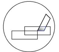
During his studies at Harvard University in 1926, Rand read a paper published in 1852 by a British doctor Dr. Herapath in 1852, which mentioned that a student of Dr. Herapath, Mr. Phelps, accidentally dropped iodine into the soluTIon disulfate of quinine, he found that there were many small green crystals immediately, Dr. Herapath put these crystals under the microscope and found the following picture: when the two crystals overlap, the light transmission The transition will change with the angle at which the crystals intersect. When they are perpendicular to each other, the light is completely absorbed (Figure 6); when they are parallel to each other, the light can be completely transmitted (Figure 7).
Figure 6: Light is completely absorbed 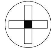
Figure 7: Light can be fully transmitted
The crystals of these iodine compounds are very small, so there are great limitations in practical application. Dr. Herapath spent nearly ten years studying how to make larger polarized crystals, but he did not succeed. Therefore, Land thought that this path might not be feasible, so he adopted the following approach:
â— Rand grinds large particle crystals into tiny crystals and suspends these small crystals in the liquid.
â— Put a plastic sheet into the above-mentioned suspension, and then put it in a magnetic or electric field to orient it.
â— Remove the plastic sheet from the suspension, and the polarized crystal will be attached to the surface of the plastic sheet.
â— Leave this plastic sheet in a magnetic or electric field, and it will become a polarizing film after drying.
Randt's method is to arrange many small polarized crystals regularly, which is equivalent to a large polarized crystal. Using the above method, he successfully made the earliest polarizing film and J film in 1928. The disadvantages of this method are time-consuming, high cost and blurry opacity. But Rand has discovered several important factors for making polarizing films: (1) Iodine (2) Polymer (3) Orientation (OrientaTIon). After continuous research and improvement, Rand finally invented the manufacturing method still in use in 1938, and the basic principles will be discussed in the next section.
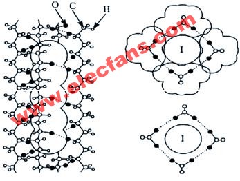
The working principle of polarizing film The most commonly used polarizing film is the H film invented by Rand in 1938. Its production method is as follows: First, a soft chemically active transparent plastic plate (usually PVA) is immersed in I2 / KI In the aqueous solution, many iodide ions diffuse into the inner PVA within a few seconds. After slight heating, they are manually or mechanically stretched until several times the length. The PVA board becomes longer and narrower and thinner. The PVA molecule was originally Irregularly distributed at any angle, after being stretched, it will gradually deflect in the direction of the force. The iodide ions attached to the PVA will also follow the directionality, forming a long chain of iodide ions. Because the iodide ion has good polarizability, it can absorb the electric field component of the beam parallel to its arrangement direction, and only let the electric field component of the beam in the vertical direction pass. Using this principle, a polarizing film can be manufactured (see FIG. 8).
Picture 8
Types and development of polarizing films The types of polarizing films used today have a wide range of applications. Not only can they be used in LCDs as polarizing materials, but also in sunglasses, anti-glare goggles, filters for photographic equipment, and automobiles Headlight anti-glare treatment and light quantity adjuster, others still have polarized microscope and special medical glasses. In order to meet the requirements of light weight and easy use, the choice of polarizing film is mainly based on the polymer dichroic type. There are four types of polarizing materials:
(1) The metal polarizing film absorbs metal salts such as gold, silver, and iron on the polymer film, and then reduces it, so that the rod-shaped metal has the ability to polarize. It is no longer produced by this method.
(2) Iodine-based polarizing film
The composition of PVA and iodine molecule is the most important method for producing polarizing film.
(3) The dye-based polarizing film absorbs the dichroic organic dye on the PVA, and extends and orients it, so that it has polarized optical performance.
(4) The polarizing film of polyethylene uses acid as a catalyst to dehydrate the PVA, so that the PVA molecule contains a certain amount of ethylene structure, and then it is extended and oriented to give it polarizing performance.
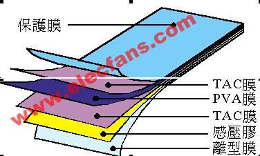
Polarizing film structure After the polymer film is stretched, the mechanical properties are usually reduced and become brittle. Therefore, after the polarizing substrate (PVA) is extended, a transparent substrate composed of triacetate fiber (TAC) should be attached on both sides to protect on the one hand and prevent the film from shrinking on the other. In addition, a layer of release film and protective film can be added to the outer layer of the substrate to facilitate bonding with the liquid crystal tank (see Figure 13).
Figure 13: The structure diagram of polarizing film
Quality characteristics of polarizing film for LCD Because of the non-luminous type of LCD display, in order to meet the requirements of bright and easily identifiable display, the polarizing film must have clear, high transmission and high polarization rotation. Recently, LCDs have become more and more widely used, such as people's livelihood, military, and high-tech. In response to the diversification of LCDs and the improvement of durability, the durability and polarization resistance of polarizing films must be strengthened.
In addition, in terms of appearance characteristics, with the improvement of LCD pixels, the surface of the polarizing film must be smooth and high-definition; if it is used for a long time under a high temperature and high humidity environment, the polarizing performance must also be maintained, and the adhesive used Its stability is also one of the main points required. Usually in the manufacturing process of polarizing film, it is carried out in a clean room:
1. Since the material of the polarizing film is PVA and TAC, there should be no foreign matter and undissolved resin on it.
2. During the laminating process of the polarizing film, no foreign matter should be mixed in during gumming, laminating and processing.
3. Materials such as protective film or release film must not have any defects.
4. There must be no foreign matter adhering to the surface and cut surface of the finished product or the packaging bag.
If the above conditions cannot be satisfied, a high-resolution, large-size, and high-definition polarizing film cannot be produced.
Development of polarizing film for LCD
(1) Iodine-based polarizing film The polarizing film composed of PVA and iodine has long occupied a considerable proportion in the LCD market. Nowadays, with the continuous improvement of materials and extension technologies, the polarization degree and transmittance are very close to the theoretical value (polarization degree 100%; transmission rate 50%).
(2) Durable polarizing film Dyestuff formula is used to make the polarizing film resistant to high temperature, high humidity and light, and most of them are used on LCDs for cars, ships or airplanes. However, its polarization rate is inferior to that of iodine and its price is its disadvantage. Today's development is through the extension of PVA alignment and the development of highly polarizing dye molecules that have uniform absorption in the visible light region. The polarizing performance is already comparable to iodine-based polarizing films, but the price is still higher than iodine-based polarizing films.
(3) Optical compensation film As the technology of LCD products is more and more advanced, the requirements for coloring, viewing angle, light leakage, etc. of the polarizing film are relatively increased. Therefore, various optical compensation films are needed for compensation. For example (STN-LCD), the polarizing film using linear polarized light may have coloring phenomenon due to the twist of liquid crystal molecules exceeding 90 degrees. The solution is to add a phase difference film.
Surface treatment Surface treatment can increase the optical and mechanical properties of the polarizing film. In order to meet the diversified requirements of LCDs today, polarizing films with composite functions have been sold on the market.
1. Anti-reflection (AR) treatment When light passes through the surface of the polarizing film, there will be a reflection loss of about 5%. Due to the loss of light and the reflected light, the visibility of the LCD will be reduced. The improved method is to deposit a layer of metal film on the surface of the polarizing film, use the principle of light interference to reduce the reflection value, and reduce the reflectivity to less than 1%.
(2) Anti-glare (AG) treatment In order to avoid excessive concentration of light, the surface of the polarizing film is processed into irregular shapes to evenly distribute the light, which can achieve the anti-glare effect.
After being processed by AG, the surface can reach a pencil hardness of 3H, which is more scratch-resistant, and has a high haze. It can be applied to large-size products (greater than 12.1 â€), mainly because of the strong backlight of the LCD. Increased requirements such as UXGA level (1600 x 1200) require more detailed treatment of AG. Currently, polarizer manufacturers are beginning to notice this aspect. I believe there will be corresponding products for market evaluation recently.
The basic method of LCD polarizer production
At present, the polarizer production technology is divided into two categories: dry method and wet hair; the PVA film is divided into two categories: dye system and iodine dyeing.
?
The dry production technology of polarizer means that the PVA film is a process method that is extended under a steam environment with certain temperature and humidity conditions. The purpose of using this process method in the early stage is to improve the production efficiency of the process and use a wider width Large PVA films are produced without breaking the film often. However, the limitation of this process is that the uniformity of the PVA film during the extension process is limited, so the composite tension, uniformity of color tone and durability of the original film of the polarizer formed are not easy to stabilize, so it is more widely used in actual production processes less. The wet production technology of polarizer means that the PVA film is dyed and stretched in a certain proportion of liquid. The early limitation of this process method is that the stable control of the PVA film extension in the liquid is difficult, so the PVA film is easily broken when processed by this process, and the width of the PVA film is limited. However, with the improvement of industrial control technology, the limitations of these wet processing processes have been greatly improved. Since the late 1990s, Japanese polarizer companies have generally adopted a 1330㎜ wide TAC film wet process Producing polarizers. Especially due to the large-scale popularization of large-size TFT-LCD products, in order to improve the utilization rate of polarizer products, the production of polarizers with a basic width of 1330 mm has become the basic method for the production of polarizers for liquid crystals. ?
The dyeing methods in the polarizer production process include iodine dyeing method and dye dyeing method. The iodine staining method refers to the use of iodine and potassium iodide as a bidirectional medium in the process of polarizing film dyeing and stretching to produce polarized polarizing characteristics of the PVA film. The advantage of this dyeing method is that it is relatively easy to obtain high polarization degree of more than 99.9% and high polarization rate of more than 42%. Therefore, most of the early polarizing material products or polarizing material products that require high polarization and high transmission characteristics are processed by the iodine dyeing process. However, the disadvantage of this process is that the molecular structure of iodine is easy to be destroyed under the condition of high temperature and high humidity, so the polarizer produced by the iodine dyeing process has poor durability, and generally can only meet the dry temperature: 80 ℃ × 500HR, Damp heat: 60 ℃ × 90% RH × 500HR working conditions below.
However, with the expansion of the use of LCD products, the requirements for the humid and hot working conditions of polarized products are becoming more and more stringent. There has been a demand for polarizer products that require working at 100 ℃ and 90% RH. The iodine dyeing process is powerless. In order to meet this technical requirement, the dyes required for the production of polarizers were first invented by Nippon Kayaku, and the dye-based high-durability polarizers were produced by Nippon Pola, a subsidiary of Nippon Kayaku. The polarizer products produced by the polarizer dyeing process using dichroic dyes can currently meet the requirements of the working conditions of dry temperature: 105 ℃ × 500HR, damp heat: 90 ℃ × 95% RH × 500HR. However, the polarizer products produced by this method generally have low polarizability and transmittance, the polarizability generally does not exceed 90%, the transmittance does not exceed 40%, and is expensive.
Telecom systems is the exchange of information over significant distances by electronic means. A complete, single telecommunications circuit consists of two stations, each equipped with a transmitter and a receiver. And we will offer the basic telecom products which you may familiar in your life to build up the telecom systems.
From Data center with a floor standing cabinets, you may get your sign out .For distribution outdoor, you may need a Waterproof Distribution Box to exchange the singals. Meanwhile, you may have a Terminal Block with 10 pair disconnection Krone Module and lighting protectors(LSA single pair type or STB Module ). When you distribute in house, there are more products in application like voice patch panels, keystone jacks, face plate, 3M connectors(like UY connectors), AMP picapond connector, wall outlets, surface mount box, and so on. Sure there is a must to get the right tool to finish operations, kinds of tools for selection: Insertion tools, Punch Tool , Crimping Tool , wire cutter, cable stripper. Hot sale for krone Insertion Tool, RJ45 crimping tools, Ericsson punch down tool, AMP picabond ratechet crimper, Coaxial Cable Crimping Tool .
We insist on compact size to ensure an easy but smart and reliable installation in every product of the telecom systems we offer. That is the final aim we work on solution, to make it perfect we also provide OEM service to satisfy your special demand. Till now, we have successfully take part in many Telecom projects in Russia, Sri Lanka, Greece, Ecuador, ect.. We have full experience in such tenders for building up telecom systems.
We keep on working just like the Cable Ring Managers to keep everything Orderly, Fast and Effective. Believe us and we will help you to be the winner !

Outdoor Distribution Box, LSA Krone Module, Mounting Frame, STB Module, Picabond Connector , Crimping Tool
NINGBO YULIANG TELECOM MUNICATIONS EQUIPMENT CO.,LTD. , https://www.yltelecom.com