
As LED production costs decline, LEDs are increasingly used in a variety of applications, including handheld devices, automotive and architectural lighting. Its high reliability (more than 50,000 hours of service life), high efficiency (175 lumens per watt) and near-instantaneous response make it an attractive source of light. However, driving LEDs is a challenging task.
Controlled brightness requires a constant current to drive the LED, and the constant current must remain constant regardless of the input voltage. Typically, LEDs have dimming requirements, for example, to adjust the brightness of a display or architectural lighting. There are two ways to implement LED dimming: changing the LED current or using pulse width modulation (PWM). The least efficient method is to change the current because the light output does not complete linearly as the current changes, and the LED spectrum changes when the current is as low as its rating.
It is important to keep in mind that human perception of brightness is exponential. It is important to make a large change in current when it is completely darkened. This has a large impact on the circuit design because the 3% regulation error at full current is 30% or higher at 10% load due to circuit tolerance. Although the response is slower, using a PWM dimming current waveform is more accurate. In lighting and display applications, it is desirable for the PWM to exceed 100 Hz so that the human eye does not feel flicker.
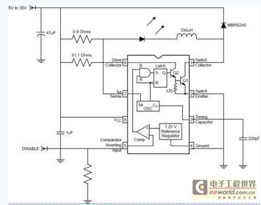
Figure 1 MC33063 constitutes a low-cost LED driver
Figure 1 shows a very simple and very low-cost buck regulator that drives a single LED that implements a fast dimming feature. It is based on an MC33063 with an internal switch, current limit comparator, oscillator and internal interface. Pins that are normally used for regulation have a shutdown function. In this case, a voltage greater than 1.25V will turn off the power, and a lower voltage will turn the power on. As the circuit is turned on, the controller operates in current limit/hysteresis mode due to the elimination of voltage feedback.
The oscillator generates a start pulse that causes the power switch to turn on. This makes the input voltage just right for current sense resistors, LEDs and inductors. When the current reaches approximately 350mA, the current limit comparator begins to sense current and turns off the power switch. The inductor voltage reverses and exceeds the input current, causing the freewheeling diode to conduct. The inductor and LED current continue to circulate until the switch turns on during the next switching cycle. This circuit is ideal for a wide range of applications. It is useful to use a 40V rated voltage and a 1.5A current switching regulator in handheld portable devices, white goods, and automotive applications that require simplicity and low cost. While implementing hysteresis control and turn-on functions can be challenging, the basic topology can be applied to a wider range of applications.
We built and tested the circuit in Figure 1. Figure 2 shows the shutdown command and the resulting LED current waveform. LEDs can easily be PWM dimmed with 500 Hertz. The rise and fall times of the current waveform are less than 100 uSec. If a higher ripple current can be tolerated in the LED, the inductance can be a smaller value and the rise and fall times can be shortened. However, the 500 Hz PWM is suitable for most applications.
Green = Output Current Blue = Off (PWM) Signal
500 uSec/div 10 uSec/div

Figure 2 Hysteresis current control provides fast PWM response
All in all, as long as it is not specifically designed to drive LEDs, switching regulators such as the MC33063 do an excellent job of dimming. Its error amplifier can be used as a shutdown function to provide LED PWM dimming, its current limit comparator provides fast response and accurate current settings, and its built-in power switch enables a small, simple circuit.
Edit: Nizi
- Perfect part to replace the cracked or scratched rear housing back cover of your phone
- housing with small parts
- Professional repair skill is needed to install this part, or search installation guides on youtube to make sure you can operate it, we will not take responsibility for any damages to this part nor your device caused by wrong installation
- With SIM card tray, mute switch, power button, volume buttons
Test:
· On-off flex cable;
· Flash;
· Charging Port & Charging flex cable ;
· Back camera;
· Volume button;
· Mute button;
· Buzzer & Vibrator;
iPhone 6/6 Plus Housing Assembly
IPhone 6 Plus Back Battery Cover,Apple IPhone 6 Plus Back Cover,IPhone 6 Plus Replacement,IPhone 6 Back Cover,IPhone 6 Back Cover Replacement,IPhone 6 Hybrid Metal Back Cover
Shenzhen Aokal Technology Co., Ltd. , https://www.aokal.com