
Guide: This article will introduce a high-photon extraction rate, high efficiency, metal-free radiator LED general illumination with LED 4Ï€ light output in combination with the research and development work of the author's company. (LEDs that can directly replace incandescent lamps and fluorescent flux lamps with considerable luminous flux Lighting) technology.
LED lighting has higher luminous efficiency and longer life; it does not contain harmful substances mercury; its service life is almost independent of the number of times the lamp is switched, and it can promote “turn off the lightsâ€; it can be instantly brightened and other outstanding advantages, and is considered to eventually replace incandescent Lamps and energy-saving lamps have become the mainstream of energy-saving lighting . In fact, only when the cost performance of LED lamps exceeds that of incandescent lamps, especially more than the currently widely used energy-saving lamps, can it become the mainstream of general-purpose lamps.
The subject of LED lighting seems to be very clear, that is, the light efficiency needs to be greatly improved under the premise of ensuring the light quality, for example, more than double the energy-saving lamp; the price needs to be greatly reduced, preferably close to the energy-saving lamp; Energy saving lamp.
Most of the current LED general illumination lamps are composed of a power LED plus a metal heat sink and a constant current driving circuit. The bulky metal radiator not only increases the cost and weight of the lamp, but also consumes a lot of aluminum resources and is environmentally friendly. An LED light is like a metal ball, which is not conducive to safety, especially high-power LED lights. Therefore, many consumers still choose energy-saving lamps when they purchase.
This article will introduce a high-photon extraction rate, high efficiency, metal-free radiator LED general illumination lamp with LED 4Ï€ light output in combination with the research and development work of the company where the author is located (LED lighting lamp that can directly replace incandescent lamps and fluorescent flux lamps with considerable luminous flux) )technology.
The LED universal illumination lamp has more than double the luminous efficiency of the fluorescent energy-saving lamp; the color rendering index can be as high as 96; the LED universal illumination lamp with luminous flux of tens to 1600 lm and higher luminous flux can be manufactured, and the L70 can have a lifetime of up to 30,000. hour. It can directly replace incandescent lamps with 10 to 100W and higher power and fluorescent energy-saving lamps with considerable luminous flux.
First, LED chip 4Ï€ light, improve PN junction light extraction rate and actual light efficiency
The energy efficiency η of the white LED illumination process is:
η = ηI × ηO × ηC × K
Where ηI : internal quantum efficiency; ηO: external quantum efficiency; ηC: photon down conversion loss; K: luminescent powder absorption.
It has been analyzed that, under ideal conditions [1], ηI = 0.95; ηO = 0.5; ηC = 0.875; K = 0.95, therefore, the highest ideal energy efficiency η = 39.5%. Here, the external quantum efficiency ηO refers to the result that photons are absorbed by chips, window materials, phosphors, lenses, etc., or reflected at the interface of different refractive index media, and then absorbed, etc., that is, light of LED elements. Extraction rate. If the optical power equivalent of 3500K warm white light is calculated as 320 lm/W, the highest luminous efficiency is 320×0.395=126 lm/W. This is obviously underestimated. But from this we can see that an important and significant potential factor for improving LED efficacy is to increase the light extraction rate.
The light of the LED comes from the PN junction of the LED chip, and its illumination is originally a natural light uniformly emitted from the 4π solid angle, but almost all LED components are currently ≤ 2π light.
LED applications range from initial indicators to digital displays and current color large-screen displays, backlit displays for liquid crystal displays, etc. In these applications, it is necessary to focus the light that was originally emitted by 4π with a reflective bowl and lens, The light that is converted to ≤ 2π, including in-line, straw hat, surface mount (SMD), and COB; such transformations are needed and correct for these applications.
However, such a transformation causes the chip to emit light that is originally emitted backwards, which will significantly reduce the extraction rate of light emitted by the PN junction, that is, reduce the actual effective light efficiency of the LED, which is not necessarily required for LEDs with ≤ 2π light output. Lighting is not required. If the LED chip 4π emits light, the extraction rate of photons generated by the LED PN junction can be significantly improved, that is, the actual light effect of the LED can be improved.
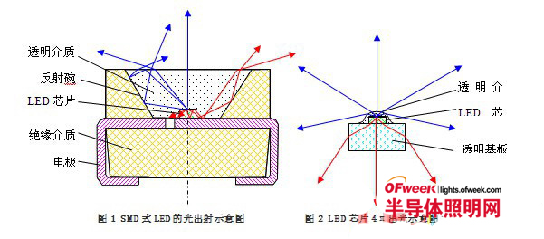
FIG. 1 is a schematic diagram of light emission of an SMD type LED which is currently widely used. The LED chip is mounted at the bottom of the light reflecting bowl, and the reflecting bowl has a transparent medium whose light exit surface is a flat surface or a curved surface (an example of a plane in Fig. 1).
A portion of the 2π solid angle light (indicated in blue) emitted by the chip PN junction can be directly emitted from the light exit window, and the other portion of the light is totally reflected by the surface of the transparent medium and then reflected by the reflective bowl or directly reflected by the reflective bowl. Among them, the direct outgoing light is about 2π[1-cos(sin-1(1/1.5)]/2π=25%, here we set the refractive index of the transparent medium to 1.5, and the light emitted by the reflective bowl is 75%. The reflectance of the reflective bowl is 0.75. If the reflection of the reflective bowl and the absorption loss of the transparent medium are not counted, the total light extraction rate is (25 + 75 × 0.75)% = 81%.
The 2Ï€ light emitted by the LED chip (indicated in red) is estimated to be approximately through the back-plated reflective film, reflective bowl bottom, reflective bowl wall reflection, multiple reflections, multiple bowl bottoms and wall absorption. 60% (depending on the reflectivity of the reflective bowl wall and bottom, the electrode surface, the dielectric surface between the electrodes, the solid crystal glue, etc.).
Therefore, the total extraction rate of the LED chip light = (0.81 + 0.6) 2Ï€ / 4Ï€ = 71%, that is, about 30% of the light is absorbed by the LED element to become thermal energy.
2 is a schematic view of the LED chip 4Ï€ emitting light. The LED chip is a transparent chip of the chip substrate, and at least one string of chips connected in series or in series and parallel is fixed on a transparent substrate of an LED light-emitting element with a transparent glue, and the chip is covered with a transparent medium layer or a luminescent powder layer.
If the chip substrate is sapphire, the epitaxial layer and the PN junction on the sapphire are GaN, the P electrode is ITO, the transparent substrate of the LED element is glass, and the transparent medium is silica gel, and their refractive indices are 1.77, 2.4, 1.8, 1.45, 1.5, respectively. It can be seen from Fig. 2 that the light of 2Ï€ of each hemisphere emitted from the PN junction of the LED chip can be smoothly emitted, and there is substantially no multiple reflection absorption inside the sapphire substrate. If the absorption of the medium is not counted, the light of the LED chip can be almost 100%. Exit.
That is, the actual luminous efficiency of the 4Ï€-exposed LED element is about (100-71)/71=41% higher than that of the SMD-type LED. Our experimental results are basically consistent with this.
It can be seen that letting the LED chip 4π emit light can improve the actual luminous efficiency of the LED element by about 40%, and at the same time reduce the heat generation of the LED. Considering the different structures of the existing LED elements, the 4π light output should be more than 30% higher than the light efficiency of ≤ 2π light.
In fact, this concept has been known to almost all LED workers, but it is not practical. The key is that it can not solve the heat dissipation problem of LED chips.
Second, gas heat analysis
In order for the LED chip to emit light, the periphery of the chip must be a transparent medium with high transmittance and heat dissipation. It is easy to think of the first thing to dissipate heat with liquids, because the thermal conductivity of liquids in transparent media is generally much higher than that of gases. For example, the thermal conductivity of water is 0.5 W/(m·K), which is 20 times the thermal conductivity of air of 0.025.
For more than ten years, people have been studying the use of liquid heat to achieve 4π light output from LED chips, but there are still some difficulties in liquid heat dissipation. For example, the viscosity coefficient of liquid is much larger than that of gas, and the viscosity coefficient of water is 8937μP. It is 10 times that of air and 77 times that of helium. The high viscosity coefficient causes the surrounding of the LED chip to be easily vaporized by the heat of the chip, and the generated gas is difficult to run off because of the high viscosity coefficient of the liquid. Surrounded by static gas, any stationary gas is a good insulator, so it is easy to overheat and burn the chip. In addition, there are problems such as liquid being easily electrolyzed, eroding chips and luminescent materials, and contamination after blistering, and there are still no good practical products.
Compared with liquid, although the thermal conductivity is low, the viscosity coefficient is much smaller than that of the liquid, and it is easy to form gas convection, which effectively dissipates the tropical heat generated when the LED is operated, thereby obtaining a good heat dissipation effect.
In the early days, LED chips were mounted on strip-shaped or flat-type transparent substrates, working in the air, and using air to dissipate heat. However, due to the low thermal conductivity of air and high viscosity coefficient, it is difficult to effectively dissipate heat. If the LED chip is mounted on a flat plate, the heat concentration is more unfavorable for heat dissipation, so it is difficult to produce an LED lamp with high luminous efficiency and sufficient output of luminous flux. For example, Ushio's LED filament lamp has an output luminous flux of only 36 lm and a luminous efficacy of only 60 lm/W [2]. Another example is the Panasonic LED chip mounted on a transparent flat plate with an air-cooling LED bulb with an output luminous flux of 210 lm and a luminous efficacy of 47 lm/W [3]. The LED bulbs of these LED chips 4π are lighter than the LED lamps made of LED elements with the existing ≤2π light output. The efficiency of the A19 bulbs with the existing LED chip ≤2π is 40-90 lm. /W, the reason is that the effective heat dissipation problem of the LED chip is not solved, resulting in an increase in the PN junction temperature of the LED chip, low light efficiency, and small output luminous flux.
The company where the author is located effectively solves the heat dissipation problem of the 4Ï€ light-emitting chip [4]. The solution is to disperse and install at least one string of LED chips of the same or different illuminating colors on a transparent substrate strip with transparent adhesive, chip and transparent. The substrate strip has at least one transparent adhesive layer or luminescent powder layer around the substrate strip; the transparent substrate has electric lead wires at two ends thereof to form an LED light strip (or LED filament); the LED light strip is installed in a vacuum sealed light transmission In the blister, the blister is filled with heat transfer with high thermal conductivity and low viscosity coefficient to protect the LED gas; the electrode of the LED is led out through the lead wire of the vacuum sealed blister core, through the LED driver and an electrical connector The connection and the electrical connector are used to connect the external power supply to form an LED filament lamp with a shape similar to that of an incandescent lamp, high luminous efficiency and no metal radiator, which can directly replace incandescent lamps and energy-saving lamps.
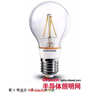
A19 LED bulbs with a total lighting efficiency of up to 170 lm/W have been produced; their output luminous flux is up to 760 lm; and the color rendering index (CRI) is up to 96. Recently, the company's laboratory has produced A19 lamps with a color temperature of 5000K, a CRI of 71, and a luminous efficacy of up to 193 lm/W. Its luminous efficiency is more than double that of energy-saving lamps. Therefore, the LED bulb with LED 4Ï€ light output and no metal heat sink enters the era of practical use. FIG. 3 is a schematic diagram of a LED filament lamp in which four LED light strips are connected in series.
The gas having a high thermal conductivity and a low viscosity coefficient is preferably a helium or neon hydrogen gas mixture. The thermal conductivity of germanium is 0.14 W/(m·K), which is 6 times that of air. The viscosity coefficient is only 194 μP [5], which is 1/8 of that of air; the thermal conductivity of hydrogen is 0.15, and the viscosity coefficient is 87.6. The cost is low, but the use is not safe; to reduce the cost, a hydrogen-halogen mixture can be used. The high thermal conductivity and low viscosity coefficient gas easily form effective convection heat dissipation, and the heat generated by the operation of the LED chip can be quickly taken away, transmitted to the bulb of the bulb, and then dissipated through the bulb to the surrounding air.
Next, a transparent substrate having a high thermal conductivity is used, such as hard glass, quartz glass, sapphire, transparent ceramic, AlN, or the like. At the same time, it is necessary to use solid crystal glue and luminescent powder glue with high thermal conductivity and high light transmittance, and reduce their thickness as much as possible, and also increase the contact area between the transparent substrate and the luminescent powder and the heat-dissipating gas to reduce the LED. The thermal resistance of the PN junction to the heat sinking gas. The at least one luminescent powder layer may be coated around the transparent substrate and the LED chip, for example, coated on the illuminating strip with the LED chip and the chipless side, or only on one side of the chip, or may be coated on the transparent substrate first. A layer of luminescent powder is coated, and the LED chip is fixed on the luminescent powder layer, and the chip is electrically connected and then coated with a luminescent powder layer.
In addition, the luminescent powder can also be coated on the inner wall of the lamp bubble shell, and the LED chip of the illuminating strip has only one layer of transparent glue, and the luminescent powder is away from the chip, which is beneficial to reducing light decay and increasing the service life of the lamp.
We can use blue plus red or orange LED chips to improve CRI, and we can also use RBG tri-color or multi-primary LED chips to make white LED strips without using luminescent powder. The chip may also be a chip substrate with a reflective film or an opaque chip. The LED light strip is still 4Ï€ light-emitting, but its light effect will be lower than that of the chip substrate. The chip can also be flip-chip LED chip, flip-chip mounted on a transparent substrate printed with an electrical connection line to form a light-emitting strip, and a high-voltage LED chip (HVLED) having a plurality of PN junctions on the chip can be used to make a light-emitting strip. Reduce the electrical connection between the chips, improve yield and production efficiency.
The luminous efficacy of this kind of LED filament lamp is more than 30% higher than that of the existing bulb lamp made of LED components with ≤2π light output, and there is no metal radiator, which can save a lot of aluminum, is more environmentally friendly, and is light in weight. Market acceptance, mass production.
However, there are also concerns that its service life is difficult to reach 30,000 hours or more, making it difficult to produce high-power LED lamps with an output luminous flux higher than 800 lm. This will be described separately below.
Third, life analysis
LED lamp life depends mainly on the operating temperature of the LED PN junction and the light decay of the luminescent powder.
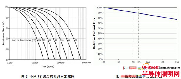
Figure 4 shows the luminous flux attenuation diagrams for different PN junction temperatures of commonly used GaN LEDs [6, 7], which are labeled with L70 lifetime at different junction temperatures. It can be seen from the figure that if the junction temperature is <85 °C, the life of L70 can reach more than 30,000 hours. The temperature of the LED PN junction is not easy to measure. The junction temperature of the PN junction can be estimated by the displacement of the main peak, the change of the junction voltage, the infrared imager, and the change in luminous efficiency.
Figure 5 shows the relationship between relative luminous flux and junction temperature [7]. It can be seen from Figure 5 that the junction temperature at a steady luminous flux of 10% lower than the cold luminous flux is 75 to 85 °C under constant LED input power. The change in luminous flux under constant power conditions, ie the change in relative light efficiency. Therefore, we can measure the initial light efficiency of the lamp and the stable light efficiency of the same input power after thermal stabilization to estimate the junction temperature of the PN junction when the LED lamp is stable. If the ratio of the stable light effect to the initial light efficiency is ≥0.9, As can be seen in Figures 4 and 5, the life of the lamp is estimated to be more than 30,000 hours. Of course, the light decay and other factors of the luminescent powder should also be taken into account; finally, it needs to be determined by actual measurement.
That is to say, the design of the LED filament lamp should satisfy the condition that the ratio of the stable light effect to the initial light effect is ≥ 0.9, and the LED filament lamp may have a service life of more than 30,000 hours.
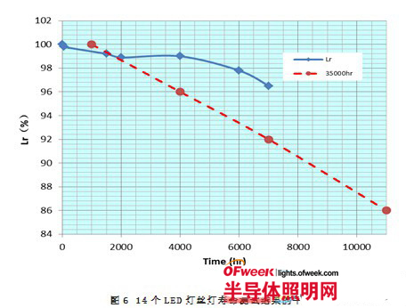
The experimental results of our life test are shown in Figure 6. The results of this experiment are the average (Lr) of 14 400 lm LED filament lamp life tests with a stable light effect and initial light effect ratio of >0.9. The dotted line in the figure is the light decay curve of Energy Star's 35,000-hour lifetime, of which 1000 hours is defined as the initial value (100%). It can be seen from FIG. 6 that the L70 life of the LED filament lamp may reach more than 30,000 hours.
Now let's take a look at the importance of filling a bulb with a high thermal conductivity and a low viscosity coefficient gas. Figure 7 shows the same 3.9W LED filament lamp. After filling the air with nearly one atmosphere of helium at room temperature and breaking the exhaust pipe into the air, the light effect changes with time under the same input power conditions. The upper curve in the figure is the test result with 氦, and the lower curve is the test result after the air is placed under the same test conditions. It can be seen from the figure that when the helium is filled, the ratio of the stable light effect to the initial light effect is >0.9. Compared with Figs. 4 and 5, the junction temperature of the PN junction is <85 °C, and the expected life can be more than 30,000 hours. < p="">
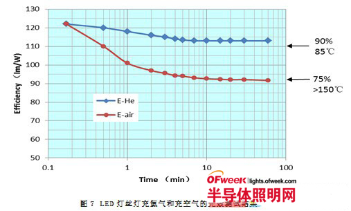
However, once the air is placed, not only its stable light efficiency is reduced by 19%, but the ratio of its stable light effect to the initial light efficiency drops to <0.75. Compared with Figure 5, the junction temperature of the pn junction is >150 °C! Obviously it is difficult to work properly. It is. Here, the importance of gas with high thermal conductivity and low viscosity coefficient can be clearly seen, and the reason why the air-filled LED filament lamp has low luminous efficiency and small luminous flux is also explained.
In addition, assuming that the life of the LED bulb is as long as 30,000 hours, if the purity of the gas in the bulb is maintained during the working period of more than 20 years, the bulb must be vacuum sealed and sealed with existing organic or inorganic rubber. It is impossible to maintain the purity of its gas for a long time. The vacuum seal can also completely isolate the influence of the surrounding environment on the LED components. The LED can work under the influence of water vapor, acid, sulfide, oxygen, PM2.5, etc. in the surrounding air, and it is more likely to last for 20 years. the above.
Fourth, ceramic tube LED light analysis
Previously, it was predicted that LED filament lamps could only produce low-power lamps below 500 lm. Such predictions are not unreasonable, because the filament lamps assembled by LED filaments (light strips) are limited by the small contact area between the LED filaments and the heat-dissipating gas, the small heat-dissipation area, and the large thermal resistance. Do >800 lm.
The goal of semiconductor lighting is to replace the 10 to 150W universal incandescent lamp and the fluorescent energy-saving lamp with its luminous flux. In fact, the only way is that semiconductor lighting can become the mainstream of general lighting. Referring to US Energy Star, the initial output luminous fluxes of 40W, 60W, 75W, 100W, and 150W incandescent lamps are 450, 800, 1100, 1600, and 2600 lm, respectively.
How to make high-power metal-free radiator LED lighting with luminous flux of 800~2600 lm? The key is to further improve the heat dissipation area of ​​LED and reduce LED PN while keeping LED 4π light, high efficiency and low heat. The thermal resistance of the cooling air that is connected to the lamp and further improve the heat dissipation capability of the bulb.
Rui Disheng's technical solution to solve this problem is [8]: the LED light bar or LED chip is directly attached to the outer wall of a transparent tube of high thermal conductivity, such as transparent ceramic tube, quartz tube, sapphire Tubes, etc., transparent ceramic tubes have a thermal conductivity of up to 23 W / (m · K), a total light transmittance of more than 95%, the thermal conductivity is close to the chip substrate sapphire, and its inner and outer surfaces are in contact with the heat-dissipating gas. The heat dissipation greatly increases the heat dissipation area of ​​the LED and reduces the thermal resistance of the LED chip PN junction to the heat dissipation gas.
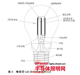
Figure 8 is a schematic view of an A19 LED bulb made of the above transparent ceramic tube LED illumination column. As shown in the figure, the LED light strip is fixed on the outer surface of a transparent ceramic tube. The upper end of the glass column on the bulb core has a spring or a bracket for fixing the upper end of the ceramic tube, and the lower end of the ceramic tube is connected with the lead line of the stem. And fixed, the stem lead wire is connected with the driver output of the lamp, the input of the driver is connected with the lamp cap, the lamp cap is used for connecting the external power source, and the LED lamp is illuminated by turning on the external power source.
9 and 10 are schematic cross-sectional views of two different configurations of LED lighting columns. 9 is a schematic view of an LED light-emitting column with an LED light-emitting strip attached to the outer surface of the transparent ceramic tube. FIG. 10 is a schematic diagram of an LED light-emitting column in which an LED chip is directly crystallized on a ceramic tube.
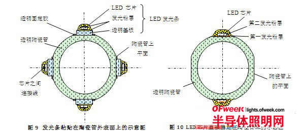
As shown in Fig. 9, at least one of the LED strips is fixed on the outer surface of the transparent ceramic tube with a transparent glue, and there are four examples of the strips. The transparent ceramic tube has a plane for mounting the light-emitting strips, and the light-emitting strips are connected in series or in series and in parallel.
Fig. 10 shows an example in which an LED chip is directly attached to a transparent ceramic tube. The LED chip is fixed on the plane of the ceramic tube previously coated with the luminescent powder layer with a transparent glue, or may be fixed on the plane of the transparent ceramic tube by a solid crystal glue mixed with the luminescent powder.
FIG. 10 shows an example in which an LED chip is fixed on a first luminescent powder layer on an outer surface of a ceramic tube, and the LED chip is covered with a second luminescent powder layer. The LED chip is directly fixed on the high thermal conductivity ceramic tube through a thin luminescent powder layer, without a transparent substrate therebetween, only a thin layer of powder glue, the sapphire substrate of the chip is substantially directly in contact with the ceramic tube, and the thermal resistance is small, further reducing The thermal resistance between the PN junction of the LED and the heat-dissipating gas can lower the operating temperature of the PN junction, improve the operating current and power of the LED chip, and increase the output luminous flux. At the same time, it is also possible to use a medium-power LED chip with a larger power to reduce the number of LED light-emitting strips and the number of LED chips, reduce the number of solid crystals and wire lines, improve production efficiency, yield and reliability, and if necessary, hit Double line to further improve reliability.
As shown in Figures 9 and 10, the light bar or chip is directly fixed on the high thermal conductivity tube, and the light bars and the chips can be kept at substantially the same operating temperature, thereby reducing the temperature rise of the individual chips. The probability of failure of the entire lamp to improve the reliability of the lamp.
9 and LED Light Bar structure shown in FIG. 10 may have various changes, e.g., with a different configuration of light bar; LED chip may be a chip with a transparent or reflective film coated backing; blue and red LED chips available or Orange LED chip to improve CRI; can also be mixed with RGB three primary color or multi-primary LED chip to make white LED light column without using luminescent powder; flip LED chip can also be used; HVLED chip can also be used; luminescent powder can also be coated The cloth is placed on the inner wall of the bulb of the bulb.
The above method can effectively improve the lamp power and output luminous flux of a single lamp. However, the final heat dissipation of the whole lamp still depends on the heat exchange between the bulb and the surrounding air. The LED light column is located in the center of the bulb, and the contact area of ​​the bulb with the surrounding air is limited, that is, the ceramic tube with a larger diameter is also difficult to manufacture. LED general illumination for greater output luminous flux.
Five, high-power multi-tube lamp analysis
Rui Disheng broke through the bottleneck with a multi-tube lamp scheme [9], enabling 800-1600 lm and higher lumens metal-free radiator LED lights to be realized. This kind of multi-tube lamp is equivalent to splitting the bulb of the single lamp into several, and there is a gap between the lamps for free flow of air, which is easy to form air convection, so that each tube can effectively dissipate heat, which greatly increases The heat exchange between the lamp and the surrounding air dissipates heat, thereby increasing lamp power and output luminous flux.
The heat dissipation scheme of the multi-tube lamp can be called the double convection heat dissipation technology of the gas convection heat dissipation in the tube and the air convection heat dissipation between the lamps, and can be made into a LED universal illumination lamp with a small volume and a higher output luminous flux without a metal radiator. At present, a multi-tube ceramic tube LED lamp with a luminous flux of 800 to 1600 lm and an experimental sample lamp with a luminous flux of up to 4000 lm have been developed.

Figure 11 shows an example of a 4-tube LED lamp with an output luminous flux of 1600 lm. Each of the lamps is vacuum-sealed and filled with a heat-dissipating protective gas having a high thermal conductivity and a low viscosity coefficient, and each of the lamps has a transparent ceramic tube LED light-emitting column; each LED tube has a constant current or current-limiting drive. It can avoid the problem that the light bulbs are inconsistent due to the LED light and the positive feedback caused by the positive feedback of the temperature, and ensure the uniformity and long service life of each lamp.
High-power LED lamps with 2 tubes, 3 tubes and 4 tubes T5 have been made. The typical parameters of the multi-tube lamp with 5000K color temperature are:
2 tube lights: 850lm, 6.4W, 133 lm/W, CRI: 81; lamp height: 110mm, maximum diameter: 40mm, weight: 58g;
3 tube lights: 1250lm, 9.3W, 134 lm/W, CRI: 82; lamp height: 110mm, maximum diameter: 48mm, weight: 64g;
4 tube lights: 1630lm, 12.2W, 134 lm / W, CRI: 81; lamp height: 110mm, maximum diameter: 52mm, weight: 70g;
It can be seen that the 6.4W 2 tube lamp is equivalent to a 60W incandescent lamp; the 12.2W 4 tube lamp is equivalent to a 100W incandescent lamp. The whole lighting effect is above 130lm/W, no metal radiator, small size and light weight. Ruidisheng's multi-tube lamps are easy to make high-power LED lighting lamps with different powers by changing the number of lamps, lamps and ceramic tubes.
Summary
The luminous efficiency of the LED chip 4π is more than 30% higher than that of the existing ≤2π emitting LED, and is cooled by a high thermal conductivity and low viscosity coefficient gas, which can be made into a high-efficiency low-power LED filament lamp; a transparent tube with high thermal conductivity The LED light-emitting column can further improve the heat dissipation capability, and make LED ceramic tube lamps with larger output luminous flux; multi-tube LEDs with dual gas convection heat dissipation technology can make LED general illumination lamps with 800-1600 lm and higher luminous flux. Its overall lighting efficiency is more than double that of energy-saving lamps, no metal radiator, low cost, light weight, long life, can replace 10-100W and higher power incandescent lamps and energy-saving lamps with considerable luminous flux. It is a new generation of LED general lighting. Due to its high luminous efficiency, simple structure and low cost, it will help promote the era of semiconductor lighting to replace incandescent lamps and energy-saving lamps, and become the mainstream of general lighting.
Made from high tenacity nylon continuous filament yarn, is bonded by the resin and finished by special heat-setting. Have superior strength, amazing stretch and recovery properties, and excellent resistance to chemical, bacteria, mildew, wear, sunlight and abrasion. AZO FREE. Our bonded nylon thread remains unbroken, and plies stay together do not split. It has better tenacity and stretch than unbonded nylon thread. For many applications, such as luggage, shoes and leather, canvas, safe bag, car seat and sporting goods, tapes edging like safety belt, parachute and other heavy duty sewing.Our company NINGBO BEILUN TIAOYUE MACHINE CO., LTD. can make the Nylon Spool according to customer's sample and drawing. ONEREEL have ablity to make the drawing and mould by ourself.
Nylon Spool
Nylon Spool, nylon netting spool, Nylon Bobbin, Nylon Tulle spool, nylon twine spool
NINGBO BEILUN TIAOYUE MACHINE CO., LTD. , https://www.spool-manufacturer.com