
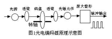
Working Principle: When the shaft of a photoelectric encoder rotates, it generates pulse outputs on both A and B channels. These two-phase pulses are separated by a 90-degree phase difference, allowing the system to determine both the direction of rotation and the speed of the motor. If the A-phase pulse leads the B-phase pulse, the encoder is rotating in the forward direction; otherwise, it is rotating backward. The Z channel produces a single pulse per revolution, serving as a reference point for counting or positioning. The A channel is used to count the number of pulses, while the B channel works in conjunction with the A channel to determine the direction of rotation.

N represents the motor speed.
n = ND measurement - ND theory
For example: If the speed of a car is 1.5 m/s, and the wheel diameter is 220 mm, then the circumference C = D × π. The motor is controlled at 21.7 revolutions per second. According to the servo system specification, the maximum motor speed is 1500 revolutions per minute. Therefore, ND = 21.7 × 60 = 1302 rpm. The number of pulses output per second by the optical code disc would be:
PD = 1302 × 100 / 60 = 2170 pulses
If the detected pulse count deviates from the calculated standard value, an incremental voltage ΔU is generated based on the relationship between voltage and pulse count. This signal is then converted via D/A conversion to adjust the input pulses accordingly, ensuring the motor maintains the desired speed.
The longer the operation time, the greater the deviation from the pre-set path. At this point, the system initiates a position loop, continuously measuring the number of pulses from the encoder and comparing it with the standard PD (ideal value). It calculates the difference ΔP and converts it into a corresponding digital output through D/A conversion. The controller then reduces the motor's input pulses, subtracts the increment from the original output voltage, and adjusts the motor speed until ΔP approaches zero. This keeps the motor within the acceptable speed range.
Based on its detection principle, encoders can be classified into optical, magnetic, inductive, and capacitive types. Depending on their scale method and output format, they can be divided into three categories: incremental, absolute, and hybrid.
1.1 Incremental Encoder
An incremental encoder uses the photoelectric conversion principle to generate three sets of square wave pulses: A, B, and Z. The A and B pulses have a 90-degree phase difference, which helps in determining the direction of rotation. The Z pulse serves as a reference point for positioning. The advantages of incremental encoders include a simple structure, long mechanical life (often exceeding tens of thousands of hours), strong anti-interference capability, high reliability, and suitability for long-distance transmission. However, they cannot provide absolute position information.
1.2 Absolute Encoder
An absolute encoder directly outputs digital signals. Its circular code disc has several concentric tracks, each composed of transparent and opaque sectors. The number of sectors doubles with each adjacent track. The number of tracks corresponds to the number of bits in the binary representation. Light sources and sensors are placed on opposite sides of the disc. As the disc rotates, each photosensitive element generates a signal based on whether it is illuminated, forming a unique binary code for each position. Unlike incremental encoders, absolute encoders do not require a counter, as they can read a fixed digital code at any position. The more tracks, the higher the resolution. For an N-bit absolute encoder, there must be N tracks. Currently, 16-bit absolute encoders are available in China.
Absolute encoders use natural binary or Gray code for photoelectric conversion. They differ from incremental encoders in that their discs have light-transmissive and opaque lines. Absolute encoders can have multiple codes, and their absolute position is determined by the code on the disc. These codes can be binary, Gray code, two’s complement, etc. Key features include:
1.2.1 Direct reading of angular coordinates;
1.2.2 No cumulative error;
1.2.3 Position data remains intact after power loss. However, the resolution depends on the number of bits, with current models offering 10-bit, 14-bit, and higher resolutions.
1.3 Hybrid Absolute Encoder
A hybrid absolute encoder provides two types of information: one set for detecting the magnetic pole position with absolute positioning capabilities, and another set that functions like an incremental encoder.
Photoelectric encoders are angle (or angular velocity) detection devices that convert the angular movement of a shaft into corresponding electrical pulses or digital signals using the photoelectric conversion principle. They offer advantages such as compact size, high precision, reliable operation, and a digital interface. They are widely used in CNC machines, rotary tables, servo drives, robots, radars, and military systems where accurate angular detection is required.
Recommended reading:
What is a Photoelectric Encoder?
Photoelectric Encoder Wiring Diagram
10KW-200KW Three-Phase Inverter
10KW-200KW Three-Phase Inverter
CHARACTERISTIC
â—Online working mode design, high speed static switching..Superior load characteristics
â—Perfect protection function
â—High performance dynamic characteristicselntelligent battery management
â—Optional battery patrol module


Nkm Hybrid Inverter With Mppt Charge,Inverter Power Inverter,Hybrid Inverter Charger,Hybrid Grid Tie Inverter
suzhou whaylan new energy technology co., ltd , https://www.xinlingvideo.com