
In the process of developing advanced process technologies, in addition to meeting the growing manufacturing requirements, semiconductor companies are faced with the growing pressure to achieve one-time success in chip design. The fab expects to design increasingly complex rules and recommendations that meet the manufacturability design (DFM) and yield-oriented design (DFY) for advanced process nodes. As far as designers are concerned, they want to minimize guardbanding while achieving optimal performance.
Increased manufacturing complexity poses greater challenges for generating vias, handling closely spaced traces, and controlling more severe nanogeometry effects. Due to these increasingly difficult interconnect design challenges, semiconductor companies receive yields typically between 40% and 70% for advanced process nodes, so that yield losses alone amount to millions of dollars. For the IC design team, these higher requirements make it a more collaborative approach. Indeed, design and manufacturing can simultaneously achieve mutual benefit from the latest “DFx†(DFM, DFY and reliability design) optimization methods.
This balanced interconnect optimization approach follows traditional layout and routing processes to improve yield, manufacturability, and timing closure during design while meeting electrical constraints and manufacturing rules.
The best DFx process available today combines DFM-aware features and post-route (pre-GDS) interconnect optimization steps in today's synthesis, placement and routing solutions.
should
Ensure integration into design intent (such as critical node information) to avoid signal integrity (SI) and timing issues after enhancing DFx. Special attention: Protect them by locking key nodes and creating a protective ring around them. This guard ring can be expressed as a protective "no entry" pitch value set for the same layer or the entire layer stack.
Perform electrical cognition/correction analysis during enhanced DFx to ensure that timing and signal integrity principles are not violated. This approach can achieve convergence after DFx optimization and ensures that the guard band of the design is not too broad in the early stages of the process.
Reasonable arrangement of DFx enhancement order. Arranging the order reasonably will help to produce the best results, as each step will lay the groundwork for the next step. For example, start with timing/signal integrity and DRC clean blocks, then apply via reduction techniques, followed by wire spreading, redundant via insertion, and closure enhancement.
Treat DFx convergence as if it were timing closure. It is recommended to implement this principle for each circuit early in the design cycle. If possible, add DFx to the entire process. Unit yield issues can be addressed early in the synthesis and layout process. When wiring, the interconnection can be made easier for lithography, OPC, and DFx. Finally, further DFx and lithography enhancements are made to the routing data using advanced methods such as space-based modeling.
Use the next generation approach, such as space-based tools that are not grid-bound, for optimal DFx enhancements.
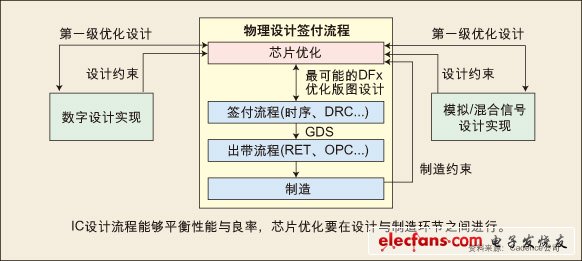
Figure: The IC design flow balances performance and yield, and chip optimization takes place between design and manufacturing.
Should not
Underestimate the importance of interconnect optimization. In addition to reducing the guard band and improving chip performance, interconnect optimization can speed up mass production and even increase yield by 6%, resulting in quantifiable benefits. For every 1% increase in yield, you can save millions of dollars, and higher production speeds can significantly affect revenue.
When evaluating the improvement effect, the vision is narrow and one-sided. For example, if vias are the source of reliability and manufacturability issues, don't just stare at those double-cut vias, check all protected and unprotected vias one by one. Protected vias are defined as redundant vias or closed tight vias. All protected and unprotected vias in the original design should be compared to all protected and unprotected vias in an optimized design.
Take it for granted that all fabs and even all process nodes are the same. In fact, each fab and each process node are different. For example, the likelihood of metal shorts and opens is different with metals such as aluminum and copper and process nodes. Allow sufficient time to evaluate the effectiveness of the previous DFx process on the new process.
The rules recommended by the fab are only considered as optional rules. Work with the fab to identify a range of factors that most affect yield. Stress patterns follow these rules and can only be violated if the design (such as timing, power) or regional targets cannot be met. Join a check/score mechanism to judge how you are doing in compliance with the proposed rules.
Perform all DFx enhancements on GDS data. Only a limited number of geometric enhancements can be achieved at this stage. DFx enhancements can be performed prior to GDS with tools that can be optimized for topology to get the best results.
Rotary ploughing Cultivator Machine:
This ploughing cultivator is centered on a rotating column and surrounded by ploughing knives. The land ploughed by our machines is very loose, the soil has been improved, fertilizer and soil conservation. Through cultivated land, the surface soil layer of a year is turned to the lower layer, so soil maturation is accelerated, which is conducive to promoting the journey of soil aggregate structure, thickening the living soil layer, deepening the cultivation layer, and increasing the living soil layer.

Rotary ploughing Cultivator Machine Technical Parameters:
1. Cutter shaft: single-axis
2. Tilling width: 2000 mm
3. Size: 2250*750*980 mm
4. Rated power: 51.5-65KW
5. Weight: 386KG
Typical Applications: can be worked in paddy field, dryland or hilly ground.
If you have any questions, please contact us directly. Crawler tractor for agriculture are produced by Hunan Nongfu with high quality and good appearance.
welcome you can visit our factory for inquiry, please send mail directly to us.
Rotary ploughing Cultivator Machine
Tiller Cultivator, Small Tractor Cultivator, mini tillage machine, rotary tiller
Hunan NongFu Machinery&Electronic.Co., Ltd. , https://www.nfagmachine.com