
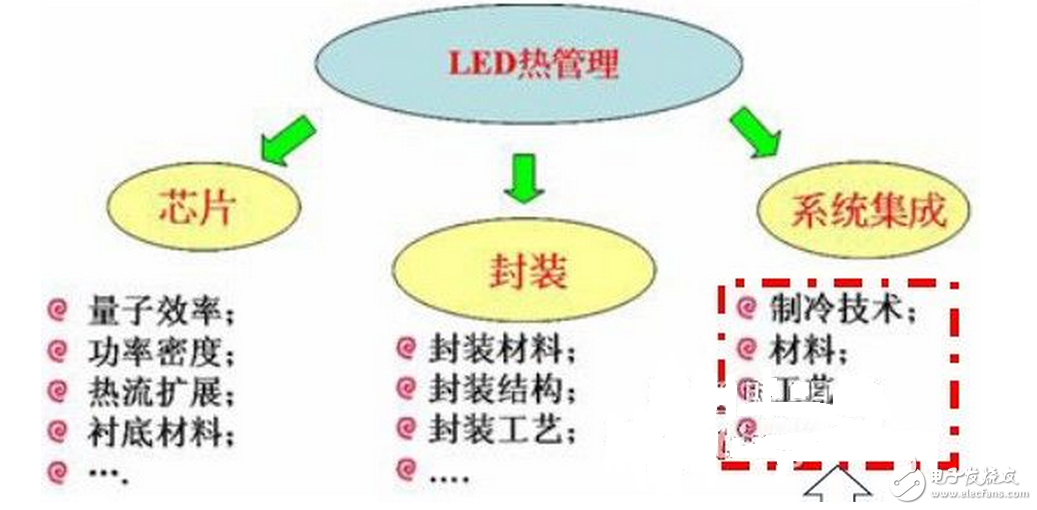
LED thermal management technologies include thermal management of chips, packaging, and system integration. On the chip side, people strive to improve the crystal quality of the material or design a new structure to improve the internal and external quantum efficiency of the chip itself, which is smaller than the conventional low thermal conductivity sapphire substrate chip.
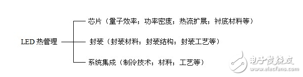
Chip (quantum efficiency; power density; heat flow expansion; substrate material, etc.)
LED thermal management package (package material; package structure; packaging process, etc.)
System integration (refrigeration technology; materials; processes, etc.)
LED heat dissipation structure description (illustration path: use illustration \ LED heat dissipation structure description)
1. The necessity of LED heat dissipation (heat dissipation is the technical bottleneck of current semiconductor lighting technology)
LED is a photoelectric device. In the working process, only 10% to 40% of the electrical energy is converted into light energy, and the rest of the electrical energy is almost converted into thermal energy, so that the temperature of the LED rises. LED temperature rise is the main cause of LED performance degradation and failure. The LED junction temperature rises, resulting in reduced luminous efficiency, poor reliability, reduced service life, and increased heat generation.
2, the solution
(A) Improve the structure and materials of LED chips and packages - the upper and middle reaches of the industry are completed
(B) System integration, mainly for heat dissipation of lamps, improving heat transfer power - work on heat dissipation design
3. Analysis of the heat dissipation structure of LED lamps
Chip (node ​​temperature control at "85 ° C) - (products with small thermal resistance are good for heat dissipation) - lamp bead substrate - aluminum substrate (increasing copper area for heat conduction) - (using thermal silica gel) - radiator lamp (Good structure for air convection) - surroundings
A few key points of LED dimming:The principle of LED illumination is different from that of traditional illumination. It is based on PN junction illumination. The same source of LED light source, because of the different chips used, the current and voltage parameters are different, so its internal wiring structure and circuit distribution are also different, resulting in various manufacturers. The requirements of the light source for dimming drivers are also different. Therefore, the mismatch between the control system and the light source and electrical appliances has become a common problem in the industry. At the same time, the diversification of LEDs also poses a higher challenge to the control system. If the control system and lighting equipment are not matched, it may cause the light to go out or flicker, and may damage the LED's drive circuit and light source.
There are five LED lighting control methods on the market:
Front edge phase cut (FPC), thyristor dimming
2. Rear edge phase-cut (RPC) MOS tube dimming
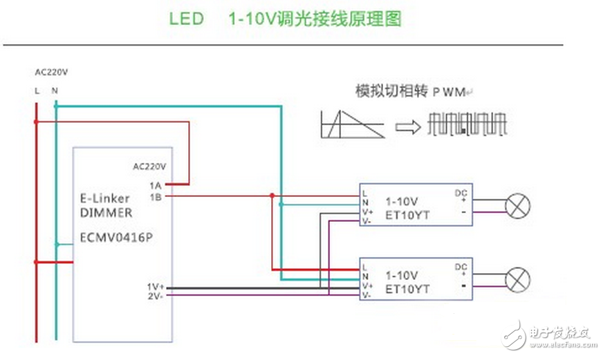
3. 1-10V dimming
4. DALI (Digital Addressable Lighting Interface)
5. DMX512 (or DMX) dimming
Front edge phase-cut control dimmingThe leading edge dimming is to use a thyristor circuit, starting from the AC phase 0, the input voltage is chopped, and the voltage input is only available when the thyristor is turned on. The principle is to adjust the conduction angle of each half wave of the alternating current to change the sinusoidal waveform, thereby changing the effective value of the alternating current, thereby achieving the purpose of dimming.
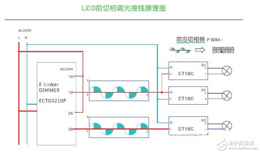
The leading edge dimmer has the advantages of high adjustment precision, high efficiency, small size, light weight and easy remote control. It is dominant in the market, and most manufacturers' products are this type of dimmer. Leading edge phase control dimmers typically use thyristors as switching devices, so they are also known as thyristor dimmers.
The advantages of using an FPC dimmer on an LED illuminator are: low dimming cost, compatibility with existing lines, and no dimming to control dimming after phase rewiring. The disadvantage is that FPC dimming performance is poor, often resulting in a reduced dimming range, and will result in the minimum required load exceeding the rated power of a single or a small number of LED lights. Because of the properties of the thyristor half-control switch, only the function of turning on the current can not completely turn off the current, even if it is adjusted to the lowest, there is still a weak current, and the characteristic of the LED micro-current illuminating makes the thyristor dimming exist in a large amount. After the shutdown, the LED still has a weak luminescence phenomenon, which has become a problem in the current promotion of the wiring-free LED dimming method. The leading edge phase-cut LED dimming driver developed by E-Linker Yilian has solved this problem very well. It is optimized by the “C-TURN OFF†technology of the drive circuit to avoid the problems of “continuous†and “stroboscopic bad lightsâ€. All kinds of lamps matching E-Linker Easy-Link front-phase LED dimming driver can be perfectly matched with other thyristor dimming systems, saving users wire and wiring man-hours, solving thyristor LED dimming matching and not The chaotic pattern of shutting down.
The trailing edge phase-cut control dimmer is fabricated using field effect transistor (FET) or insulated gate bipolar transistor (IGBT) devices. The trailing edge phase-cut dimmer generally uses a MOSFET as a switching device, so it is also called a MOSFET dimmer, commonly known as a "MOS tube." The MOSFET is a fully controlled switch that can be controlled either on or off, so there is no thyristor dimmer that cannot be completely turned off. Another MOSFET dimming circuit is more suitable for capacitive load dimming than thyristor, but because of the high cost and relatively complicated dimming circuit, it is not easy to be stable, so the MOS tube dimming method has not developed, thyristor tuning Optical devices still occupy the vast majority of the dimming system market.
Compared to leading-edge phase-cut dimmers, trailing-edge phase-cut dimmers are used in LED lighting equipment, and because there is no minimum load requirement, better performance can be achieved in a single lighting device or very small loads, however, Since MOS tubes are rarely used in dimming systems, they are generally only made into knob-type single-lamp dimmer switches. This low-power rear-cut phase dimmer is not suitable for engineering applications. Many lighting manufacturers use this dimmer to do dimming tests on their own dimming drivers and lamps. Then, the dimming products of their own are pushed to the engineering market, which leads to the situation that the phase-cut dimming drive is modulated by the thyristor dimming system. This mismatch in dimming mode causes dimming to flicker, which can quickly damage the power supply or dimmer.
1-10V dimmingThere are two independent circuits in the 1-10V dimming device, one is the ordinary voltage circuit for turning on or off the power to the lighting device, and the other is the low voltage circuit, which provides the reference voltage to tell the lighting device the dimming level. 0-10V dimming controller is often used in the dimming control of fluorescent lamps. Now, because a constant power supply is added to the LED driver module and there is a special control circuit, the 0-10V dimmer can also support A large number of LED lights. However, the application disadvantages are also very obvious. The low-voltage control signal requires an additional set of lines, which greatly increases the requirements for construction.
Small size MCX connectors are snap-on coupling micro-minature coaxial connectors with 30% smaller size than SMB connectors. The out body with Brass, gold plated material, Male center contacts with brass and Female center contact with Beryllium copper, which areusre to fit most applications where space, weight, performace and easy to assembly.
MCX Semi-Rigid Cable Connector,MCX Comformtable Semi Cable Connector,MCX Cable Assembly Connector,MCX Cables Connector
Xi'an KNT Scien-tech Co., Ltd , https://www.honorconnector.com