
Visual Development Tool Technology Using MiniGUI of GEF
1 Overview
With the wide application of embedded systems, the status of graphical user interface (GUI) in embedded systems is becoming more and more important.
At present, relatively mature embedded GUI systems include MicroWindows, Qt / Embedded, MiniGUI, etc. MicroWindows has good portability, and the development focuses on the underlying graphics engine, but the functions of the window system and graphics interface are still lacking. Qt / Embedded has good portability. The X Window program based on Qt can be easily transplanted to an embedded system, but it has high requirements on system hardware, and is mainly used for handheld devices. MiniGUI was originally designed and developed for industrial control systems. It has strong customization capabilities, fast speed, and good performance. It is especially suitable for occasions with high real-time requirements.
Due to the limitations of embedded system hardware resources, the basic requirements for embedded system GUI include: less resource consumption, high performance, high reliability, and configurable. The visual development tool designed in this paper selects MiniGUI as the graphical interface support system.
MiniGUI is a purely free software that complies with LGPL terms. It is a graphical interface support system tailored to the application characteristics of embedded systems and has been widely used. It provides a complete multi-window mechanism and messaging mechanism, as well as dialog boxes and commonly used control classes, including text boxes, buttons, edit boxes, list boxes, etc .; very compact, the library file containing all functions is only about 300 KB.
Traditional MiniGUI program development is based on a text editor. Developers cannot see the overall effect of windows and controls in the process of program source code writing, and they lack a visual development environment. Therefore, this article designs a MiniGUI visual development tool, and uses Eclipse GEF (GraphicaI Ediring Framework) to achieve.
2 Overall design of visual development tools
2.1 Functional requirements
Visual development tools should provide interface layout design functions, including: the placement of controls on the interface, the setting of attributes, the definition of callback functions for each control; menu, status bar, bitmap editing; response to interactions that occur during the editing of the interface Events, such as drop / drag, undo / redo, move, delete, resize, etc .; save and parse the corresponding layout function; generate and run MiniGUI source code according to user design.
2.2 Overall structure
Visual development tools are mainly composed of interface design tools and source code generation tools. The overall structure is shown in Figure 1. 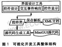
Interface design tool: implements the WYSIWYG interface editor function, which can change and adjust the displayed content and form according to the needs, which makes the creation of the user interface very convenient. The traditional object-oriented design method is used to develop the visual interface, which will encounter problems such as user interface and underlying data hybridization and class expansion caused by interface expansion. Therefore, the interface design tool uses MVC pattern design. The user sets the control properties through the "control design" of the interface design tool; the "interactive event response" is used to respond to the interactive events that occur during the editing of the interface and complete the modification of the control properties. These two parts correspond to the Controller in MVC. "Control class" stores various properties of the control, corresponding to Model. "Control display" sets the display control according to the properties of the control class, corresponding to the View. The XML document is responsible for saving the interface layout, and the control class can also parse the document content according to the XML to get its own attributes.
Source code generation tool: generate the corresponding MiniGUI source code by traversing the attributes of all control classes, and arranging the graphical user interface layout according to the requirements of the operating platform (currently only RTEMS is supported).
2.3 Organizational structure
All control classes are managed in the form of a tree. The top layer of the tree represents a management project, which includes all dialog boxes, menus, status bars, and bitmap resources. The child nodes of the dialog box are all the controls displayed on it. The menu includes pop-up menus and menu items. The status bar and The dialog box is similar, and the tree structure is shown in Figure 2. Since the XML document will be parsed by Java into a tree structure, the process of parsing the interface layout is a tree traversal process. Using a tree structure to organize the control classes can make the software logically easy to understand, the control organization relationship is clear and clear, and the interface layout and source code can be saved through the tree traversal. 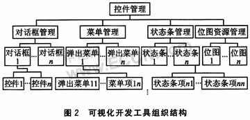
Because many elements in the graphical user interface have common attributes, this article abstracts the common attributes and methods of these elements as the base class. Mainly use 2 base classes: container class Content and control class Control. Content mainly includes methods such as container ID, text attributes, and saving parsing controls; Control mainly includes properties such as control ID, position size, and control style, as well as methods for saving parsing controls and generating source code. Among them, the dialog box, menu, status bar and bitmap inherit from Content, as shown in Figure 3 (a); the dialog box control inherits from Control, as shown in Figure 3 (b). When generating source code and other operations, the entire interface project is traversed from top to bottom, and the methods of the base class can be directly called without distinguishing the specific categories of controls. This improves code reuse and reduces redundant code. 
3 System implementation
GEF is based on the MVC framework, which can easily implement the basic functions of drop / drag, undo / redo, move, delete, resize and other graphic editors, and provides common layouts, which are very suitable for developing WYSIWYG interface editing Device. Among them, GEF's EditPart corresponds to the Controller in MVC, and Figure corresponds to the View.
This tool is developed based on GEF, which can minimize the development workload and enhance the stability of the software. At the same time, Java development makes this tool can run on any system with a Java virtual machine, with good cross-platform.
3.1 Interface design tool based on GEF
This tool provides menu, status bar, bitmap, and dialog box controls (including CheckBox, ComboBox, PushButton, RadioButton, MonthCalendar, GridView, M1Edit, ProgressBar, Property-Sheet, StaTIc, StaTIcBox, TreeView, TrackBar, SpinBox, etc.) Editing function. The modification of the control can be done through the property page and direct operation on the interface. The edit on the property page informs the Model through the setPropertyValue method of the IPropertySource interface. The Model then notifies the EditPart to make changes through the firePropertyChange method of the PropertyChangeSupport class; the changes from the interface are encapsulated as a request and distributed to the EditPart. The EditPart then modifies the data in the Model through the command After the data is modified, the Model informs the EditPart that the data has been modified; after receiving the notification of the Property change, the EditPart performs corresponding operations according to the modified data type (such as redrawing the figure, etc.).
Take the operation of CheckBox as an example to illustrate the control process flow based on GEF, as shown in Figure 4. Among them, operation A is to drag a new CheckBox from the toolbox to the Dialog; operation B is to modify the text (Text) displayed by the CheckBox through the property page; operation C is to change its size directly by dragging and dropping the selected CheckBox. Operations A1 to A4, B1 to B3, and C1 to C3 are specific execution flows. 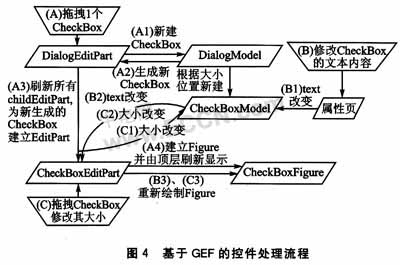
3.2 Graphic display problems
In GEF, each view can respond to interactive events only within the effective range of its parent view. If the model is directly organized according to the control relationship of MiniGUI, the interface design tool cannot complete the interaction with the user well.
Taking the menu as an example, the code to generate the menu part in MiniGUI only needs to complete a tree traversal. Each non-leaf node of this tree is a pop-up menu, the leaf node is a normal menu item, and the root node is a virtual node, used to connect the entire menu in series, as shown in Figure 5 (a). Each node is called MenuItem. This tree structure is shown in Figure 5 (b) as shown in Figure 5 (b) when the GEF is displayed according to the Model, where Figurell is the childFigure of Figurel. In GEF, only the childFigure is included in the effective range of parentFigure, the request for childFigure can be dispatched by its parentFigure to the corresponding Controller of childFigure, and reflected to the Model, as shown in Figure 5 (c). Obviously, the tree structure cannot meet the needs of modifying menu items. Therefore, a linked list structure composed of Menu is added to the tree structure formed by MenuItem, and each MenuItem adds a Parent pointer to its own MenuItem, such as As shown in Figure 5 (d). Each Menu (ij) record includes all MenuItem (ij, k), and creates its own Menultem (i, j). MenuItem (ij, k) represents the kth MenuItem belonging to Menu (ij), and Menu (ij) represents the subordinate Menu expanded by MenuItem (i, j). All Menus form a linked list. GEF displays the contents of this linked list instead of the original MenuItem tree. In this way, the Figure corresponding to each MenuItem can be included in its parentFigure, and the corresponding controller can also receive requests uploaded from the interface. 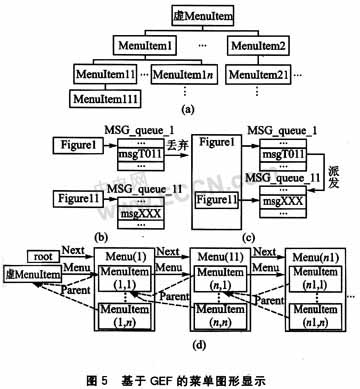
By changing the MenuItem property to PopUp, you can create a sub-menu for it. The flow of creating a new function is as follows (the parameter is the MenuItem whose current property is modified to PopUp): 
Create a new MenuItem function for Menu: 
The Figure corresponding to Menultem should also provide the method DimensiongetPreferredSize (int hint, int hint2), which is used to obtain the new size and position of Figure caused by the MenuItem property change.
The EditPart of Menu should also provide the following methods:
â‘ Redraw yourself and all the MenuItems and their subordinate Menus below. The function Rectangle CalcMenuSize (MenuEditPart) is used to get a rectangle that can accommodate all MenuItems included. 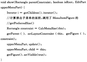
â‘¡ Recursively change all Menus that are currently visible and their corresponding MenuItem to invisible in the subordinate Menu of the MenuEditPart to be updated. 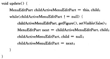
3.3 Data storage
Extensible Markup Language (Extensible Markup Language, XML) has the following advantages over other format languages: It has good extensibility, allowing users to create and use their own defined tags to define the types and properties of controls; tree storage The structure and good self-description are very suitable for describing interface elements; the flexibility of XML provides a structured data representation method, which makes the user interface separate from structured data.
Therefore, the interface design tool stores the interface design results in XML format. Since Java provides classes for XML document generation and parsing, it simplifies coding workload and enhances software reliability.
Examples are as follows: 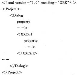
The outermost Project indicates that the inner layer is the layout of the interface, the second layer Dialog indicates that the inner layer corresponds to a dialog layout, and the third layer consists of multiple
4 Experimental results
The operation interface of the visualization tool is shown in Figure 6. On the left is the project management area, you can see all the interface layouts established by the current project. The editing area in the middle is an open dialog layout, where you can perform operations such as drop / drag, undo / redo, move, delete, and resize of the control. On the right is the control property editing area, used to modify the control properties (such as ID, text style, border, etc.). 
Conclusion
This article designs a MiniGUI visual development tool, which is realized by Eclipse GEF. Users can use this tool to visually design and modify the graphical user interface. At the same time, they can expand their own controls and define the properties of the controls to enrich the interface's manifestation. Experiments show that this tool runs well and stable in the actual system and effectively improves The development efficiency of the graphical user interface.
Strong Suction Vacuum Cleaner,Strong Suction Robot Vacuum Cleaner,Strong Suction Wired Vacuum Cleaner,High Power Vacuum Cleaner
NingBo CaiNiao Intelligent Technology Co., LTD , https://www.intelligentnewbot.com