
introduction
With the continuous development of USB communication technology, the USB interface has been widely used. Single-function USB devices, such as USB keyboards, USB mice, and USB modems, can no longer meet people's requirements for USB device functions. Multi-functional USB devices are constantly emerging, and common ones include USB cameras with microphones and USB video phones. Therefore, it is necessary to study multi-function USB devices to meet people's demand for new USB devices.
In view of the shortcomings of the single function of human-machine interface devices such as mouse and keyboard, which cannot fully meet the needs of modern society, a design method of multi-function USB device is proposed. A multi-function USB device is a complicated USB device. Although it has only one USB interface, it has the function of realizing multiple types of devices. Taking the USB multimedia keyboard encoder HT82K95E as the core, the enumeration process of two human-machine interface devices is completed. The two basic design methods of USB composite device and USB combination device are also compared, and the realization of USB combination device is introduced in detail.
1 Structure model of multi-function USB device
Multi-function USB devices are usually implemented by connecting different types of devices through a single or multiple USB controllers. There are two methods for implementing multiple devices on a USB interface: one is a Compound Device and one is a Composite Device. Figures 1 and 2 give the structural models of composite equipment and combined equipment, respectively.
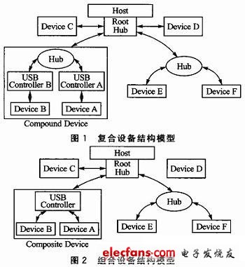
In fact, USB devices should be treated as different functions. Multiple functions can be packaged together to form a physical device. Therefore, the composite device is actually a single device formed by several devices through a USB Hub. The Hub in the composite device and each function connected to the Hub will allocate their own device addresses. A combined device is a device with multiple interfaces. Each interface represents an independent device, but the combined device has only one device address.
When a multi-device USB device is developed using a composite device method, the development process is the same as developing two different types of USB devices, and the development difficulty is relatively low. This article focuses on the design method of the combined equipment and implements it with examples.
2 Design method of combined equipment
2.1 Characteristics of combined equipment
A USB combined device refers to a USB device that has multiple interfaces and is independent of each other. A USB device has only one device address, and different functions can be mapped to different interfaces to develop a multi-function USB device.
The combined device adopts a USB control chip, which is connected to the A device and the B device at the same time. The host can communicate with the A device and the B device at the same time.
2.2 Descriptor structure of the combined device
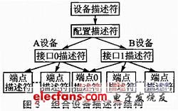
As shown in FIG. 3, taking the combined device of two interfaces as an example, the descriptor structure of the combined device is explained. There is one configuration descriptor under one device descriptor, and there can be multiple interface descriptors under one configuration descriptor, corresponding to different devices. Each interface descriptor contains multiple endpoint descriptors. A USB logical device is a set of endpoints for a USB system. Endpoints can be classified according to the interface they implement. All USB devices need to implement a default control method. This method uses endpoint 0 as the input endpoint and also uses endpoint 0 as the output endpoint. The USB system uses this default method to initialize and generally use logical devices (that is, to set up this device). Devices can have endpoints other than endpoint 0, depending on the implementation of these devices. In addition to endpoint 0, low-speed devices can only have 2 additional optional endpoints. The number of additional endpoints that a high-speed device can have is limited only by the definition of the protocol. Except for the default endpoint of the default control channel, other endpoints can only be used after the device is set. In addition to endpoint 0, other endpoints cannot be shared between different interfaces.
The combination device uses a USB control chip to communicate with different devices by controlling different interfaces, which solves the problem of distinguishing the data flow between the host and each device in the combination device.
3 Hardware implementation of combined equipment
3.1 USB interface part
The device adopts Holtek's 8-bit USB multimedia keyboard encoder HT82K95E as the core of this system. HID devices such as mice and keyboards are low-speed devices. Therefore, in order for this device to be able to achieve both-way transmission of mouse and keyboard data with a PC, the MCU must first have a low-speed USB interface and support 3 endpoints (including endpoint 0). Comprehensive consideration, HT82K95E was selected as the main control chip of this system. Since both mouse and keyboard are low-speed devices, a 1.5kΩ pull-up resistor should be added to the USB signal line.
3.2 MCU part
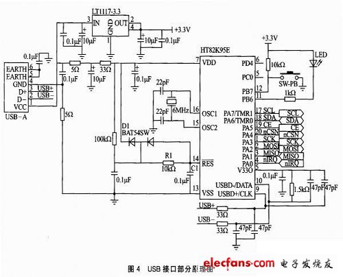
The schematic diagram of the USB interface is shown in Figure 4. The reset circuit of the MCU uses the RC integration circuit composed of R1 and C1 to realize the power-on reset function. At the moment of power-on, since the voltage of the capacitor cannot be changed suddenly, the reset pin is low, and then the capacitor starts to charge slowly, the potential of the reset pin starts to rise, and finally becomes high, completing the power-on reset of the chip. The HT82K95E microcontroller also contains a low voltage reset circuit (LVR) for monitoring the supply voltage of the device. If the power supply voltage of the device falls within the range of 0.9VLVR and exceeds 1 ms. Then the LVR will automatically reset the device.
It should be noted that for the reset circuit of the device, a BAT54SW diode should also be added, and the connection method is shown as D1 in FIG. 4. If D1 is not added, the device can be reset normally when it is used for the first time, but cannot be reset normally in future use, because the charge in the capacitor cannot be discharged, and D1 can quickly discharge the charge in the capacitor through the entire circuit .
The combined device adopts the HT82K95E USB control chip, and realizes the functions of mouse and keyboard by managing the two interfaces.
Seat Tube Battery,Inner Seat Tube Battery,Seat Battery Packs,Electric Bike Battery 24V
Changxing Deli Technology Co., Ltd. , https://www.delipowers.com