
The research goal of this paper is to design H. The Exp-Golomb decoder in the 264 standard proposes an efficient and low-cost ASIC implementation scheme based on an in-depth discussion of its algorithm.
Exp-Golomb coding principle and decoding algorithm analysis
At H. In the 264 basic specification, except for the residual transformation coefficients using the CAVLC encoding method, all other syntax elements are encoded using Exp-Golomb. Exp-Golomb encoding is a regular variable-length encoding method, which is widely used in various video encoding standards. Exp-Golomb coding is based on the probability statistics of symbols. Short code words are used to indicate information with high probability of occurrence, and long code words are used to indicate information with low probability of occurrence. The code length has an exponential correspondence with the number to be encoded, so that the overall The average codeword is the shortest. Compared with fixed-length coding, it saves a lot of storage space.
At H. In 264, the 0th order Exp-Golomb coding is adopted. The coding rules are shown in Figure 1.
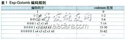
The logical structure of the Exp-Golomb codeword is: [M zeros] [1] [INFO]. Among them, M 0s and 1s in the middle are called prefixes, and INFO is the information value of M bits. Therefore, the length of each Exp-Golomb codeword is 2M + 1. Each index word codenum can correspond to a code word structured as above, and the relationship between them is:
codenum = 2M + INFO-1 (1)
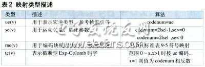
It can be seen from Equation 1, that by performing Exp-Golomb decoding, the number of consecutive Os before the codeword can be detected first, and then the suffix is ​​taken out, and the codenum value can be obtained by calculation by the formula. At H. There are four types of Exp-Golomb codes in 264: unsigned ue (v), signed se (v), mapped me (v), and truncated te (v). Therefore, for the resolved codenum value, there are four mapping methods according to the different types of syntax elements, as shown in Table 2. After the mapping is completed according to the corresponding description, the output syntax is the decoded value.
Exp-Golomb decoder hardware structure design
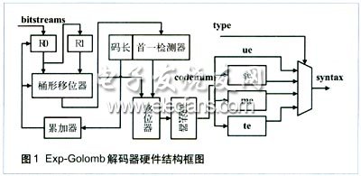
The hardware structure of the Exp-Golomb decoder designed based on the above decoding algorithm is shown in Figure 1. The entire system is mainly composed of the following modules: input code stream buffer shift module, code length detection module, codenum generation module, and syntax element mapping module. After the system is powered on and reset, the code stream buffer shift module first provides the word to be decoded, and then the first detector in the code length detection module detects the number of consecutive 0s, and the current code length is calculated immediately and sent to the accumulator . At the same time, the result of the first detection is sent to the codenum calculation module together with the word to be decoded, and the codenum value is obtained by shifting and subtraction. Finally, the codenum is sent to the four mapping units for processing, and the final decoding syntax element is output to the register by the selector. The entire decoding process is completed in one clock cycle. The hardware structure of each functional sub-module will be described in detail below.
Input code stream buffer shift module
The input code stream buffer shift module is to realize H. The key module of 264 real-time decoding. Since the code length cannot be determined in advance in each variable-length decoding process, the next code word must be located while solving the code value. This requires that the module has the characteristics of fast response and parallel output. Because H. The maximum code length of the Exp-Golomb code defined in 264 does not exceed 32. The design uses two 32-bit registers, a 32-bit barrel shifter and an accumulator to achieve this function, as shown in the left end of Figure 1. Among them, the register Rn is responsible for reading data from an external module, and used as the input of the barrel shifter together with the register R1; in each decoding cycle, the barrel shifter moves out of the decoded stream while loading a new to be decoded Stream; while the accumulator counts the processed code length, transmits the shift length of the barrel shifter, and determines and controls the reading of R0 and the update of R1. This provides a continuous and uninterrupted code stream for subsequent processing units.
Iphone Lightning Cable with Lightning Connector Sync and charge your iPhone, iPad, or iPod with faster speed.
The Iphone Charger Cable could meets your need for any place . Its length contains 3tf , 6ft , 10ft , etc .
Our customers and the media all agree on one thing: this cable is one of the best iPhone Lightning cables in the world.
This iPhone charger cable boasts increased durability, faster charging, faster data transfer and compatibility with almost all cases. Give your iPhone the treatment it deserves.
iPhone Lightning Cable compatible with IOS devices that have a Lightning port, including iPhone 8 /7 / 6 / 6s,iPhone 8 Plus / 7 Plus / 6 Plus / 6s Plus, iPhone 5 / 5C / 5S, iPad with Retina display, For iPad mini, iPad Air, iPad Pro, iPod nano 7th Gen and iPod touch 6th Generation.
The iPhone charger cable which with Original 8 Pin connector with a lightning end has lightning-fast data transfer , retro comfortable, soft and elastic,strong, durable ,dirt , no deformation.
We are committed to providing professional, safe and stable mobile powers for our customers .
Iphone Lightning Cable
Iphone Lightning Cable,Iphone Charger Cable,Iphone 6 Charger Cable,Long Iphone Lightning Cable,Apple Iphone Charger Cable,Iphone Usb Cable
Hebei Baisiwei Import&Export Trade Co., LTD. , https://www.baisiweicable.com