
CAN communication relies on synchronous data transmission, where the CAN controller continuously performs bit synchronization. However, different data communication systems have varying needs when it comes to bit timing accuracy. To meet these requirements, a deeper understanding of time period specifications is essential.
Time period specifications are tailored based on the system's requirements. To achieve the maximum bus length at a given bit rate or minimize latency (i.e., maximize bit rate for a fixed bus length), the phase buffer segment must be minimized. When this segment is set to its minimum value, only a phase error of |e| = 1 can be corrected during resynchronization. This imposes strict synchronization demands, typically requiring a high-precision quartz crystal with an error margin below 0.1%.
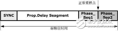
Figure 1 illustrates the time period specification for the maximum bit rate and bus length product, commonly used in industrial automation systems. These stringent requirements ensure reliable communication over long distances without signal degradation.
If the bit rate and bus length requirements are less demanding, the product of the two can be reduced, allowing for a longer time buffer segment. This enables correction of larger phase errors, such as |e| = 4, during a single resynchronization. As a result, more cost-effective ceramic oscillators can be used. Figure 2 shows the time period specifications for automotive electronics, where higher oscillator tolerances are acceptable.
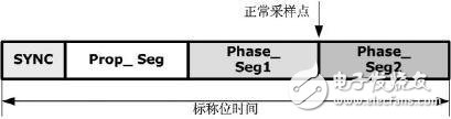
Figure 2: Time period specification for maximum oscillator error.
Bit timing specifications are typically defined based on the required bit rate. The bit time must be an integer multiple of the system clock period, expressed as tbit = n × tq, where n ranges from 4 to 25, and tq represents the time unit. One approach is to first determine the length of the propagation segment, taking into account the maximum bus length and internal delay. The round-trip delay is then converted into corresponding time units and rounded to the nearest multiple of tq. Since the synchronization segment is fixed at 1 tq, the remaining two phase buffer segments are calculated as (tbit - tprog_seg - tq). If the number of remaining time units m is even, both segments are equal. If odd, one segment will be extended by one tq.
It's also important to consider the minimum nominal length of Phase_Seg2, as it must be sufficient to accommodate the CAN controller’s data processing time—typically between 0 and 2 tq. The sync jump width (SJW) is usually set to its maximum allowable value, which is Min{4, tPhase_Seg1 / tq}.
Oscillator tolerance is determined using two key formulas. The first formula ensures that the frequency deviation remains within acceptable limits:
Df ≤ tSJW / (20 × tBit)
Where: tBit is the nominal bit time, and tSJW is the resynchronization jump width.
The second formula accounts for the phase segments and ensures stability:
Df ≤ min{tPhase_seg1, tPhase_seg2} / (2 × (13 × tBit - tPhase_seg2))
Earth anchors are used in a variety of applications including:
- Retaining wall reinforcement
- Temporary structural support for buildings and tents
- Secured tie down anchorage for floating docks and pipelines
- Utility pole and tower anchors
- Erosion control anchoring
Earth Anchors,M22 M16 Stay Rod Anchor,Galvanized Steel Rod,Hdg Adjustable Anchor Rod
Shahe Yipeng Import and Export trading Co., LTD , https://www.yppolelinehardware.com