
The micro-hyperspectral system is a new application method combining hyperspectral camera, microscope, computer, etc., and the microscopic scale of the sample to be tested can be further improved by the microscope structure at different magnifications, and the substance can be fully observed on the microscopic scale. The image information, in order to further obtain the spectral information of the material, thus taking full advantage of the advantages of hyperspectral in the spectrum and image, combined with the micro-mechanism system, further expands the application of hyperspectral technology.
First, the test principle and method
Hyperspectral imaging technology is a very narrow-band image data technology developed in the past two decades. Its most prominent application is in the field of remote sensing detection, and it has a greater application prospect in more and more civilian fields. It integrates advanced technologies in the fields of optics, optoelectronics, electronics, information processing, and computer science. It is an emerging technology that combines traditional two-dimensional imaging technology with spectral technology.
Hyperspectral imaging is defined as the use of imaging spectrometers in the spectral range of tens or hundreds of spectral bands in the spectral range from ultraviolet to near-infrared (200-2500 nm) over multispectral imaging. The target object is continuously imaged. At the same time as obtaining the spatial feature of the object, the spectral information of the measured object is also obtained.

Target object - imaging objective lens - incident slit - collimating lens - PGP - focusing lens - CCD prism - grating - prism: PGP
Figure 1 Imaging schematic
The spectral resolution of the spectrometer is determined by the width of the slit and the linear dispersion produced by the optical spectrometer. The minimum spectral resolution is determined by the imaging performance of the optical system (point spread size).
The imaging process is: each time a line on the line (X direction), during the process of detecting the conveyor belt advancement, the arranged detectors sweep out a strip track to complete the longitudinal scan (Y direction). The three-dimensional hyperspectral image data of the sample can be obtained by combining the horizontal and vertical scanning information.

Figure 2 like a cube
Second, test analysis
Red red LED sample test:
Test conditions: Current: 220mA Voltage: 1.89V
Camera parameters: 1392x520 (spatial dimension x spectral dimension) Exposure time: 0.1ms Spectral range: 400-1000nm
Spectral resolution: 3.6nm Spectral calibration file reference attachment
Microscope: Magnification: 10X Objective
Distance between the surface of the sample and the surface of the objective lens: 1.6cm
Imaging mode: reflection imaging mode
Microscope source spectrum range: 350nm-2500nm
The following illustration is a red (red) LED hyperspectral image information and spectral information taken using a microscopic hyperspectral system. The part seems a bit fuzzy, which is caused by the uneven surface of the sample under the high magnification objective lens. The sharper part of the image is the state where the camera and the microscope system are in focus, and some blurred areas are slightly deviated. Focus position, a clear picture of multiple different focus positions is listed in the figure below.

Figure mobile phone taking microscope eyepiece photo

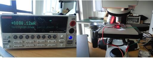


Figure 3 Characteristic spectrum of the Red LED source

Figure 4 Red LED light source at 662.8nm grayscale image
What are IC Sockets?
Most of our everyday electrical devices contain integrated circuits (ICs) or chips which are installed on the printed circuit board (PCB). Most chips are soldered directly onto the board but sometimes they need to be interchangeable, or removed, and this is when an IC socket is used.
The IC socket fits onto the board and holds the chip, protecting it from heat damage which could be caused by soldering. Programmable chips are a great example where IC sockets are used, allowing removal for testing, programming or replacement due to failure.
IC (Integrated circuit) Sockets
IC Sockets connector is designed to provide a compressive interconnect between component leads and a printed circuit board (PCB). This connector is designed to provide a compressive interconnect between component leads and a printed circuit board (PCB). It simplifies the board design, enables simple reprogramming and expansion and easy repair and replacement, and offers a cost-effective solution without the risk of direct soldering. With a wide range of solutions for land grid array (LGA) and pin grid array (PGA) sockets, this connector features contact tip geometry optimized to reduce risk of contact damage during handling and package installation.
Antenk offer a comprehensive range of DIP, SIP and PGA sockets to suit most multiple electrical applications.
Types of IC Sockets
DIL /DIP– Dual in-line. These have two parallel rows of pins, available in various numbers to match the relevant IC and are normally very cost effective. A larger socket can be created by placing two smaller ones together, end-to-end, e.g. two 8-pins become 16-pin.
SIL/SIP – Single in-line. This socket has a single line of pins and are frequently used in smaller applications like resistor arrays or boards with short lead pins, such as a desktop computer. There are many different sizes and attributes available.
PGA – Pin Grid Array Sockets. Complex printed circuits are too valuable to risk direct soldering to expensive integrated circuits (ICs). Using a socket is the answer. The use of sockets offers advantages that prove cost effective and simplify board design.
DIMM – Dual In-line Memory Module. Random Access Memory (RAM) can be easily installed in computers or laptops using DIMM sockets. These are important components that help to ensure reliable connectivity. They have two separate rows of electrical contacts or pins on either side. It`s a general rule that the more pins the higher the RAM it supports. There are various pin sizes available.
SIMM – Single In-line Memory Module. These have a single row of pins which connect memory modules to circuit boards. They are space saving and can be installed at predetermined angles with positive polarisation to prevent memory modules from being inserted incorrectly. They are used mainly in older computers dating from the 1980s to late 1990s. Available in various sizes and number of pins.


IC Sockets Connector/Integrated Circuit Sockets Typical Applications
In notebook and desktop computers, LGA sockets feature a robust bolster plate for reliable connection to the microprocessor package while limiting PCB bowing during compression.
In servers, our mPGA and PGA sockets -- with custom arrays available in more than 1,000 positions --offer zero insertion force (ZIF) interface to the microprocessor PGA package and attach to the PCB with surface-mount technology (SMT) soldering. Antenk's IC sockets are designed for higher performance CPU processors.
IC Sockets,Ic Socket Connectors,Pin IC Socket,Pin IC Socket Connector,IC Sockets Adapters,IC Sockets & Plugs,Integrated circuit Sockets,IC Sockets and Headers
ShenZhen Antenk Electronics Co,Ltd , https://www.antenk.com