
The CANbus bus protocol is known for its high stability and high fault tolerance. However, there are still many users who are worried that CAN will receive the wrong information when using it. The CRC check is added to the data. Is there any way to do this? Is the CAN receiving the wrong data if necessary?
The transmission of information has always been a matter of great concern to mankind. From the most primitive body language to high-end electronic signals, the methods of information transmission vary. The pursuit of information security has not changed since ancient times. In the Western Zhou Dynasty, the "Tai Gong Bing Law" has the design of "Yin Fu" and "Yin Shu" to ensure the security of information.

Figure 1 makes people worry about information security
In our industrial production, the method to ensure the correct transmission of signals is even more varied. Adopting the CAN protocol in the information transfer process is a common solution to reduce the error rate. So, the question is, can the CAN protocol He De can make the transmitted signal not go wrong? Let us analyze it in depth here. The CANScope bus synthesis analyzer is used to capture a frame of CAN messages as follows:
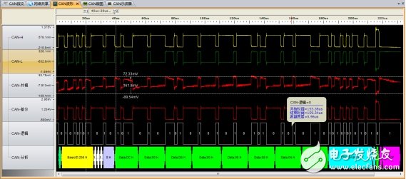
Figure 2 CANScope bus integrated analyzer captured message
It can be seen from the figure that the CAN protocol adopts the method of differential signal transmission, which can effectively prevent the shielding interference from the outside. In the protocol analysis part of the last line, we observed that a frame of signal was split into segments of different colors. What exactly does each segment mean? The secret to ensure that the signal is transmitted correctly is hidden in these paragraphs. Let's take a look at the analysis of Kenting's cattle.
· Data header: At the beginning of the data, it is a 1-bit header, indicating that the data frame starts.
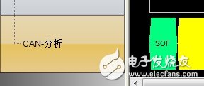
Figure 3 data head
· Arbitration segment: It marks the priority of the data of this frame, which contains an ID code. The smaller the ID code value in the arbitration segment, the higher the priority of the frame data. The CAN controller will listen to the cable while sending data. The upper level state, if the level of the arbitration bit is found to be inconsistent with the level issued by the node, the transmission is abandoned and the right to use the bus is discarded. This design can improve bus utilization and allow important information to be sent first.

Figure 4 arbitration segment
· Control segment: A total of six digits, used to indicate the length of the data. There are reserved bits in the control section of the data for future protocol rule extensions.
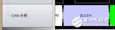
Figure 5 control segment
· Data segment: After the previous padding, the data segment encodes the information that the frame data needs to convey. A frame signal can transmit 0-8 bits of data, 8 bits per byte. Short and precise to ensure the real-time information.

Figure 6 data segment
· CRC segment: The CRC segment is a key to ensuring data accuracy (knocking at the blackboard). To prevent the signal from being altered for some reason, a CRC check is added to the data link layer of the CAN. The sending node calculates a CRC value according to the content of the transmission and fills in the CRC segment for transmission, and the corresponding receiving node also calculates the received data, and compares the calculated CRC value with the received one. It is your own person who can get the secret number. If the comparison is wrong, it means that there is a problem with the transmitted signal, and you need to feedback the error message. This mechanism ensures that CAN does not receive erroneous information and its security is unquestionable.

Figure 7 CRC segment
· ACK segment: used to indicate whether the signal is received correctly. A normal node will send a dominant bit in the first bit of the ACK. According to the state of the ACK, the sending node can know whether the data is successfully transmitted. If the transmission fails, the sending node will decide whether to retransmit according to its own status.

Figure 8 ACK segment
· End of frame: consists of 7 recessive bits, indicating the end of the frame.

Figure 9 ends
After such an analysis of the smashing, the message structure of CAN is clearly displayed in front of us. Due to the presence of the CRC segment, the probability of CAN errors is very small.
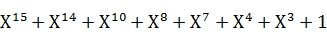
The CRC polynomial used in the CRC check can detect up to 5 discrete errors, or find burst errors that occur by chance of less than 15 bits. The CRC check calculates the bit sequence of the SOF bit, the arbitration segment, the control segment, and the data segment, but does not consider the padding. The 15-bit check sequence specified in the CAN protocol is derived from the BCH code, which is a cyclic code that is particularly suitable for message lengths below 127 bits. The 15-bit polynomial applied in the CAN protocol is as follows:
After transmitting or receiving the last bit of the received data field, the CRC register contains the CRC sequence to be transmitted or to be received. Dividing the calculated CRC sequence from the received CRC sequence allows the receiver to identify possible CRC errors.
Some engineers are worried that the CAN will receive the wrong information and do the CRC check in the data. I don't know that the CAN link has been self-provided in the data link layer CAN, and the CRC check is added to the data. There is no need for it.

The CAN bus not only specifies the differential transmission specification of the physical layer, but also specifies the packet verification rule of the data link layer. Both of these are automatically completed by hardware. When receiving, there is no need to consider whether there is an error, as long as the buffer is received. Take out the data, CAN CRC check can guarantee the error rate is below 10-9, which is undoubtedly a very safe and reliable transmission protocol.

The CAN bus has very good advantages in real-time transmission of signals. The CANscope bus analyzer can well complete the troubleshooting and detection calibration of the CAN bus. Thanks to its core technology, Zhiyuan Electronics can solve all kinds of difficult problems in the industrial field for users and look forward to growing with you.
Specialized Slip Ring,Slip Ring Rotary Joint,Slip Ring Induction Motor Rotor,Induction Motor Slip Ring
Dongguan Oubaibo Technology Co., Ltd. , https://www.sliproubos.com