
The USB interface has been an essential element of the infotainment architecture, so manufacturers have embraced this already consumer-centric interface with stricter protection requirements. Automakers continue to use infotainment systems as an extension of the multimedia experience. There is a need to prevent short-circuiting of the vehicle battery during assembly, manufacturing or maintenance. For example, when the long wire harness that connects the head unit to a different connection module is damaged, all pins can be shorted to a 12V car battery. Other potential failure mechanisms include the use of non-compliant adapters, cables or chargers; mechanical distortion of the USB connector or cable; or any debris that enters the connector and shorts the data line to VBUS.
This article refers to the address: http://
In the first part of a two-part series, I will illustrate the best way to prevent short-circuit faults in USB circuit cells. In my next post, I will extend the best way to optimize your car's USB battery short-circuit design.
When designing a battery-proof short-circuit USB, always keep in mind three main aspects:
• Protect the bandwidth of your solution.
• Clamp voltage and response time behavior.
• Overcurrent and short-to-ground characteristics.
In the past, it was impossible to find a USB 2.0 anti-battery short-circuit solution that would solve all three aspects, but TI's new TPD3S714-Q1 series of anti-battery short-circuit protection devices can help solve these common problems.
bandwidth
Signal integrity is one of the biggest challenges designers face in automotive USB applications. Since USB 2.0 supports data transfer rates of up to 480 Mbps, any small amount of capacitance added to the wires can distort the signal, causing data transfer failures. This complicates the designer's task in finding a solution that not only protects sensitive electronics from high voltage and current spikes, but also maintains optimal signal integrity.
The TPD3S714-Q1 is a single-chip solution for VBUS and data line protection against battery shorts, short circuits and electrostatic discharge (ESD) for USB connectors. The integrated data exchange provides twice the high bandwidth for minimal signal attenuation while providing up to 18V protection against battery short-circuit. Figure 1 is an insertion loss diagram highlighting high-speed data exchange using a 1GHz-3dB bandwidth.
Figure 1: TPD3S714-Q1 Data Exchange Differential Bandwidth
You can use an eye diagram to analyze the effect of line capacitance on bandwidth. Measuring minimum and maximum voltage levels and jitter can expose any problems in USB data line transmission. The high 1GHz bandwidth allows for USB 2.0 high speed applications. A small margin above the 720MHz bandwidth also helps maintain a common clear USB 2.0 eye diagram with a long stay in the automotive USB environment. Figure 2 is an example of a USB 2.0 eye diagram.
Figure 2: USB 2.0 Eye Diagram of the TPD3S714-Q1
Clamping voltage and response time
Although bandwidth is one of the most important features to remember when choosing a protection solution, you must also ensure that the clamp voltage is low enough to protect against any battery shorts or ESD events in downstream circuits. In addition, you should design overvoltage field-effect transistors (FETs) with fast turn-off times to quickly protect the upstream system-on-chip (SoC) from unwanted voltage and current spikes (SoCs).
Battery short-circuit protection isolates the system's internal circuitry from any overvoltage conditions present at the VBUS, D+, and D- pins. On these pins, the TPD3S714-Q1 handles overvoltages up to 18V for hot swap and DC events. Overvoltage protection circuitry provides the industry's most reliable protection against battery short-circuit isolation, helping to improve system-level protection. Figure 3 shows its 5V clamp voltage during a short-to-18V fault, emphasizing the ultra-fast response time of 200ns on the data path.

Figure 3: TPD3S714-Q1 data conversion short circuit to 18V response waveform
Overcurrent and short to ground
Choosing a bad overcurrent protection circuit will hinder the rapid launch of the product. During an overcurrent event, the amount of significant current flowing through the system side may cause the upstream 5V rail to power down or power down, and potentially reduce or reset multiple integrated circuits (ICs) connected to the shared rail. The purpose of the overcurrent protection device is to limit the amount of current that can be drawn by the USB port, such as in a short to ground condition. In addition, the USB 2.0 specification requires the use of overcurrent protection in any USB powered design.
Figure 4 depicts a short-to-ground event where the system voltage drops to less than 200mV, maintains the stability of the shared 5V rail, and properly isolates the fault. The TPD3S714-Q1 integrates an accurate current limit load switch of up to 0.5A to automatically limit the current during an overcurrent event. The internal FET switch prevents excess current from flowing through the upstream device, preventing system side reset.
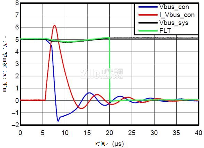
Figure 4: TPD3S714-Q1 VBUS short-to-ground response waveform
Remember – when looking for a USB 2.0 battery short-circuit solution, always keep in mind the protection device's bandwidth, clamping voltage and response time, as well as overcurrent and short-to-ground characteristics. Taking into account these key areas will make it easier for OEMs to achieve their goals and reduce time to market.
Solar Panel,Poly Solar Panel,Mono Solar Panel,Solar Panel For Power Stations
Fuzhou Mei Li Cheng Imp&Exp Co., Ltd , https://www.mlc-solar.com