This means that system power consumption is a critical design metric for designers, and they will need to spend a lot of time researching product data sheets from different chip vendors. This task is a lot of work because there are many variables in the data sheet that affect power consumption, and in many cases, manufacturers do not provide similar comparisons between products. In fact, the design of the audio input and output subsystems is particularly tricky because they contain both analog and digital circuits and typically use multiple independent power supplies.
This article refers to the address: http://
Easy to misinterpret data
A more in-depth analysis of the audio subsystem circuitry helps to understand the true meaning of the power consumption data in the audio IC manufacturer's data sheet. Figure 1 shows the main functional modules involved in the audio output section of a portable system. Typically, the last modules in this chain (digital signal enhancement, digital-to-analog conversion, analog mixing and amplification) are integrated into a single device, the "audio DAC." The data sheet will provide "DAC power" or "DAC supply current" data, and it is important to determine if this data includes the power requirements of the amplifier and other DAC-related subcircuits. If it is not included, it needs to be calculated separately.
Similarly, the “headphone playback†power consumption in the data sheet typically does not include on-chip enhancement circuitry such as clipping, 3D signal enhancement, and equalization circuitry. Power-supply data from vendors often does not include these circuits to make their devices look better than competitors. Some manufacturers do not include a digital audio interface even when defining playback power consumption, which is quite different from actual usage because the interface must be powered up to receive audio data for playback.
The fact that system architecture changes further increases design complexity. For example, the volume control can be implemented by software on the digital portion of the audio chip CPU, or an analog programmable gain amplifier on the audio chip. As a rule of thumb, it is good practice to explicitly design the relevant functions of the system, determine which physical device is responsible for the function, and correctly calculate the power consumption of each function.
 |
| Figure 1: Functional block diagram of audio playback and the factors that affect the power consumption of each module. |
Real world load and signal characteristics
There are other data in the data sheet that often do not match the actual situation. For example, the power consumption of speakers and headphones during playback is a large fraction of the overall system power consumption, but these data are usually not included in the data sheet. More commonly, the data sheet provides power consumption data in a "silent" state, which is represented by a long string of zeros in the digital domain. In this state, the voltage on the load is zero and there is no load current. In addition, the audio IC itself consumes very little power in the mute state, which further reduces the externally claimed power consumption, sometimes even when the load is not connected.
In order to get meaningful data, the system must be connected to the load. In the consumer electronics field, the impedance of a small speaker is typically 8 ohms and the impedance of the headphones is 16 ohms or 32 ohms. In addition, the actual test signal must also be fully driven to reach the load through all relevant components in the circuit.
A 1 kHz sine wave is easy to generate and is often used as a test signal, but this signal does not reflect the frequency mixing or amplitude variation characteristics that typically characterize music or speech over time. Perhaps the most useful signal is the signal specified for the IEC 60268-5 (formerly IEC 268-5) standard for loudspeakers. This standard uses so-called "pink" noise, which is a weighted mixture of various frequencies running over the entire audio band. The “creep factorâ€, the difference between the peak and long-term RMS amplitude, is well defined in “pink†noise, which reflects the change in actual signal between loud and silent.
Defining signal amplitude
Regardless of which test signal is used, its amplitude will have a large impact on power consumption, which is another area that is confusing because there are many ways to define the signal amplitude. For example, "dBV" is relative to the root mean square 1V, and "dBFS" is relative to "full scale", for any given audio component. It is difficult to make meaningful comparisons using decibel numbers for different references or definitions that do not explicitly specify a reference. Since people are ultimately concerned with the power supplied to the load, it is important to define the amplitude of the signal at a given load impedance in watts or milliwatts.
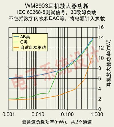
Since the efficiency of any given amplifier will change as the signal amplitude changes, the amplifier power dissipation needs to be considered over the entire dynamic range of the signal, as shown in Figure 2. For example, Class G amplifiers choose to use different supply voltages depending on the signal amplitude, and the efficiency is usually not continuous near the transition point.
 |
| Figure 2: Efficiency of the headphone amplifier (take the Wolfson Microelectronics WM8?03 audio codec as an example). |

10 Port Usb Charger,10 Port Usb Charging Hub,120W Higher Power Charger,Multi Port Usb Charging Station
shenzhen ns-idae technology co.,ltd , https://www.best-charger.com
