
Guide: This program uses pyroelectric infrared detector, light brightness and sound control sensor as the sensing device of the illumination area, carries out signal acquisition, converts the collected signal to the STC12C56 28AD single-chip microcomputer through the conversion circuit, and the control signal processed by the single-chip microcomputer Control the drive circuit.
AC LED intelligent lighting system provides convenience for people's daily life lighting, avoiding circuit failure caused by frequent switching. AC LED lighting does not add an AC/DC converter like DC LED lamps, which reduces the cost and improves the system. Performance has achieved the goal of energy saving. It also avoids the dilemma that the LED light source itself is not broken and the AC-DC converter is broken first. Therefore, AC LED lighting can be widely used in building interior lighting and street lighting.
The LED light source has the advantages of power saving, low power consumption, high luminous efficiency and long life. Compared with traditional incandescent lamps and fluorescent lamps, it effectively saves energy. It is considered to be the green lighting source of the 21st century. The current LED light source is a low voltage (VF=2~3.6 V), high current (IF=200~1 500 mA) semiconductor device, and must provide suitable DC to be able to emit light normally, because we use 220 V every day. High-voltage AC, so you must use the buck technology to get a lower voltage. It is common to use a transformer or switching power supply to step down, then turn the AC into DC, and then turn it into a DC constant current source to illuminate the LED source. Therefore, the system scheme of DC driving LED light source must be transformer + rectification (or switching power supply) + constant current source. These two scheme systems will have 15%~30% power loss. If the LED light source is directly driven by AC, the system efficiency will easily reach 90% or more. At present, most of the lighting fixtures in public buildings still use manual switches, which have high failure rate and are only suitable for incandescent lamps. They are not suitable for the use of LED lights and other lighting facilities. Below we introduce a set of AC based on sensor and microcontroller control. Direct drive LED lighting system design.
1 AC LED light source works
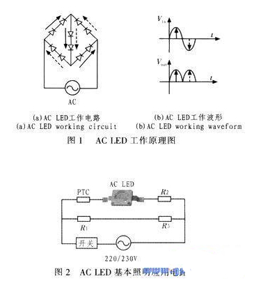
The working principle of the AC LED light source is shown in Figure 1(a). The LED input and output voltage waveforms are shown in Figure 1(b). A stack of LED micro-die is divided into 5 strings by using an interlaced matrix arrangement process. The AC LED chip string is similar to a rectifier bridge. The two ends of the rectifier bridge are respectively connected to the AC power supply, and the other ends are connected to the LED die. The positive half-circle uses solid arrows to indicate the direction of current flow, and there are 3 strings of LED crystals. The negative half-cycle uses dashed arrows to indicate the direction of current flow, and 3 strings of LEDs emit light. The LEDs on the 4 bridges are illuminated. The string of LEDs is always illuminated due to sharing. It alternately illuminates at 50 times per second at 50 Hz. The rectifier bridge obtains pulsating DC, and the LED's illumination is also flashing. The LED has the characteristics of power-off afterglow, and the afterglow can be kept for tens of microseconds. Because the human eye is inert to the flow point memory, the result is human. The interpretation of the operation of the LED light source + afterglow is continuous illumination. The LED on the bridge arm is half working, and half of the time is resting, so the heat is reduced by 20% to 40%, so the life of the AC LED is longer than the DC LED. Even if the middle string of LEDs fails, it is usually a breakdown short-circuit fault. After the breakdown, the resistance is small, and the LED illumination on the bridge arm is not affected, but the brightness of the lamp is slightly lowered. Therefore, this design technique is reasonably mature. Mature products of AC LEDs such as Seoul Semiconductor's AC110 V AX3201, operating current of 40 mA; AC220 V AX3221 and AX3231, operating current of 20 mA are widely used for lighting. Compared to DC LEDs, energy consumption is greatly reduced.
2 general AC LED lighting application circuit
The electrical schematic diagram of the typical application of AC LED is shown in Figure 2. It is very simple. The positive temperature coefficient thermistor PTC and the current limiting resistors R1, R2 and R3 are connected to the ends of the AC LED respectively, and 110 V or 220 is connected. V communication can enter the lighting work.
When the LED is mass-produced, its impedance has a certain degree of dispersion. The AC LED light source manufacturer will perform the impedance division on the mass-produced products at the factory. When the customer is using it, it can be checked according to the binning table provided by the LED light source manufacturer. Resistance limiting resistor.
3 intelligent AC LED lighting system hardware design
The block diagram of the system working principle is shown in Figure 3. The thermal infrared sensor, the glare sensor and the sound sensor are used as the sensing system. The sensor signal is transmitted to the main control device (CPU) STC12C5628AD after A/D conversion. After the device processes, the control signal is added to the D/A conversion circuit, and the control signal is amplified by the amplification circuit and applied to the driving circuit composed of the thyristor, and the thyristor driving circuit controls the opening and closing of the AC LED lamp and Brightness.

3.1 Passive pyroelectric infrared detector
The detector has three key components: Fresnel filter wafer, which passes through the filter chip with a cut-off wavelength of 8~12é˜, and acts as a bandpass filter, so that the environmental interference is obviously controlled; Fresnel lens Focusing, that is, the pyroelectric infrared signal is refracted (reflected) on the pyroelectric infrared sensor. The second function is to divide the warning zone into several bright and dark zones, so that the moving objects entering the warning zone can The form of temperature change stores a pyroelectric infrared signal on the pyroelectric infrared sensor, so that the pyroelectric infrared sensor can generate a changing electrical signal, and the pyroelectric infrared sensor converts the change of the infrared radiation energy of the filtered optical chip. The electrical signal is completed, the thermoelectric conversion is completed, and the software solidified in the system performs arithmetic processing on the collected data, and the control software in the control system determines whether to issue the light-on signal through the control logic.
3.2 Ambient brightness sensor
The core device of this sensing module is a photoresistor. The spectral response peak of the photoresistor is closer to the wavelength of the human visual sensitive area. And when the intensity of the illumination is weakened, its response time is relatively increased, and the output state remains relatively stable when the illumination intensity changes. Therefore, a photoresistor is selected among a plurality of photodetectors. Considering that the photoresistor is sensitive to temperature changes, the resistor in the bias circuit can adopt a photoresistor similar to the temperature coefficient of the detector element to prevent the operating point from drifting.
3.3 voice sensor
The voice control sensor is composed of a voice sensor, an audio amplifier, a frequency selection circuit, a delay open circuit and a thyristor circuit. The relative comparison of the sounds is used to determine whether to start the control circuit, and the regulator can adjust the initiality of the given voice sensor. Value, the voice sensor continuously compares the intensity of the external sound with a given intensity. When a given intensity is exceeded, a "sound" signal is sent to the host, otherwise a "no sound" signal is sent.
3.4 Intelligent control circuit
The control system adopts STC12C5628AD single-chip microcomputer, which is a single clock/machine cycle (IT), high-speed/low-power/super-anti-interference new-generation 8051 single-chip microcomputer. The instruction code is fully compatible with the traditional 8051, but the speed is 8~12 times faster. Integrated MAX810 dedicated reset circuit 4-channel PWM, 8-channel high-speed 10-bit A/D conversion, widely used in motor control, strong interference occasions. China's lighting network technology papers · Intelligent lighting selection This type of microcontroller mainly considers the role of PWM and AD conversion, so that the peripheral circuit has been greatly simplified, and the generated PWM signal can be directly connected to the drive circuit, reducing the cost of the system . China Lighting Network Technical Paper·Intelligent Lighting System According to the national standard civil building lighting design standard (GBJI33-90), we control the indoor brightness at around 200lx. This design sets up 3 sets of sensing systems and strict software control. The working method is as follows.
First, it is detected by passive pyroelectric infrared detectors and environmental noise detection, and the ambient brightness is detected. If there is no one, all the LED lights are not turned on. If there are some people, they are divided into two cases: if the illumination of the environment to be illuminated is greater than 200 lx, the LED lighting fixtures are turned off; if the illumination of the environment to be illuminated is less than 200 lx, The LED lights are all on; whether it needs to be turned on according to the size of the sound.
3.5 AC LED driver circuit
AC LED driver circuit adopts the trigger circuit with bidirectional thyristor as the core device. After the D/A conversion of the output signal of the MCU, it is amplified by the operational amplifier, then the bidirectional thyristor circuit is connected, and the bidirectional thyristor circuit is connected. ACLED lighting circuit. According to the size of the output signal of the single chip microcomputer, the conduction angle of the thyristor is controlled, and the degree of conduction of the thyristor circuit determines the opening and closing of the AC LED illumination and the control of the illumination brightness.
4 system software design
The program adopts the modular design idea, and sets the function module subroutine with the main program as the core, which simplifies the design structure. During the running process, each function module subroutine is called by the main program. Because the real-time requirements of the lamp control are not high, the cycle control can meet the requirements. The software of the system mainly completes the following functions: the signal input module realizes the corresponding sensor signal input into the data channel of the single chip microcomputer, and in the control system software, the infrared detector signal and the sound control sensor signal are respectively digitized by rectification and amplification, and processed into the Boolean data of the switch. Then, the phase or the rectified and amplified environment fills the light, and the signal generated by the light intensity detecting system is compared with the output generated by the first two signals, thereby generating a switching signal that determines the switch of the lamp.
5 Verification of design results
In the design process, each unit circuit is tested, tested and adjusted. Then, the whole circuit is adjusted and tested. Through the overall test of the system, the circuit works safely and reliably, and the work is reliable. The design requirements have been met and the purpose of intelligent lighting has been achieved. Since the DC LED AC-DC conversion is omitted, the efficiency of the test system can reach over 93%.
6 Conclusion
According to the characteristics of the AC LED circuit, the drive circuit is designed with the bidirectional thyristor as the core device, and the system can realize the intelligent opening and brightness adjustment of the AC LED illumination. After the actual circuit test, the circuit works stably and reliably, and meets the design requirements.
About silicone watch bands:
With the development of the society,people demand more and more high standard of live. In the same time,we can find out from their decorations, they are also beginning to pay attention to product safety and environmental protection, for example silicone watch bands. The Silicone Watch Band made of food grade silicone,It is very safe and good for the environment. Its texture is soft and durable,it can be clean easily and its dirty resistance is very good! many athletes and the office workers like it,even the old or young!
The following silicone watch bands photos for your reference:

Silicone Watch Band
Waterproof Watch Strap,Silicone Rubber Strap,Casio Watch Bands,Sport Strap Watch Band,Apple Watch Bands
OK Silicone Gift Co., Ltd. , https://www.oemsiliconegift.com