
Introduction
This application note describes the main features of the ADSP-CM408F Analog-to-Digital Converter Controller (ADCC) module, focusing on the relevance and usability of this product in current feedback systems for high-performance motor control applications.
The purpose of this application note is to emphasize the key features of the analog-to-digital converter (DAC) module and to provide configuration guidelines for motor control applications. This article provides code examples that demonstrate the ADI ADCC driver.
For more details on all of the ADCC's features, configuration registers, and application programming interfaces (APIs), see the ADSP-CM402F/ADSP-CM403F/ADSP-CM407F/ADSP-CM408F product page and use ARM Cortex-M4 and 16-bit The ADSP-CM40x Mixed Signal Control Processor Hardware Reference Guide for ARM Cortex-M4 is available on the product page of the ADSP-CM40x Mixed Signal Control Processor for ADC development products.
Although this application note focuses on current feedback, similar configurations and application principles apply equally to feedback and measurement of other signals.
Similarly, although this application note focuses on the ADSP-CM408F, the principles are equally applicable to other products in the ADSP-CM402F/ ADSP-CM403F/ADSP-CM407F/ADSP-CM408F series.
Current feedback system overview
An example of current feedback in a motor control application is shown in Figure 1. This configuration is often used for high-performance motor drives and samples the motor phase winding current instead of sampling the low-end phase pin of the inverter. At medium to high levels, current sensors or transformers (CT0 and CT1) must be used for the current measurement path because the resistive shunt is oversized and inefficient.
In the configuration of Figure 1, the processor is located on the low side of the safety barrier, and signal isolation is typically inherent to CT0 and CT1, and there is digital isolation between the microprocessor's pulse width modulated PWM output and the gate driver.
Some signal conditioning is typically required between the current sensor output and the ADC input for range matching and high frequency noise filtering. The conditioned current measurement signal is then applied to the ADC input for sampling and conversion. Performing a winding current measurement on each ADC input will enable simultaneous sampling of current measurements for higher control loop accuracy for enhanced performance. In addition, the sampling time can be directly synchronized with the PWM sync pulse in the hardware.
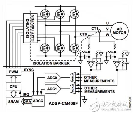
Figure 1. Current feedback of the ADSP-CM408F ADC in motor control
These features enable precise timing of phase current measurement points during the PWM period. Aligning these measurement instants with the midpoint of the zero vector or the midpoint of the PWM period ensures that the current sampling level is equivalent to ignoring the instantaneous average current of the switching ripple.
Synchronous U-phase and V-phase samples at the midpoint of the zero vector and the midpoint of the PWM period are shown in Figure 2.
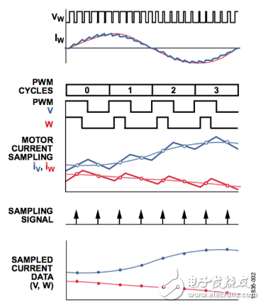
Figure 2. Average current sampling plot
Weighing display is an instrument that displays the mass and weighing status of the weighed object in electronic instrument.
The current weighing display is digital display.
Weighing Indicator,Weighing Digital Indicator,Industrial Digital Indicator,Wireless Weighing Indicator
Ningbo Santwell Imp & Exp Co.,Ltd , https://www.santwell.com