
With the improvement of people's living standards and the development of technology, home intelligence has become an inevitable trend and has penetrated into thousands of households. Smart home is the smart home (Smart Home), also known as digital family (Digital Family), home automation (Home AutomaTIon), electronic home (E-home), intelligent home (Intelligent Home), network home (Network Home) , Intelligent House (Wise House, WH), Intelligent Building (Intelligent Building), etc. It is a system that uses computers, communications, networks, power automation, information, structured wiring, wireless and other technologies to interconnect all different equipment applications and integrated functions. It takes the residence as a platform, and has the functions of construction, network appliances, communication, home appliance automation, telemedicine, home office, entertainment and other functions. It integrates system, structure, service, and management as a safety, convenience, comfort, energy saving, entertainment, and high efficiency , An environmentally friendly living environment. It is divided from the control level and is generally composed of a central control center, a home intelligent control terminal, a community intelligent control system, a home gateway, and an external network.

1 Smart home system architecture
The home system is mainly composed of intelligent lighting control, intelligent home appliance control, intelligent security alarm, intelligent entertainment system, visual intercom system, remote monitoring system, remote medical monitoring system, etc. The block diagram is shown in Figure 1.
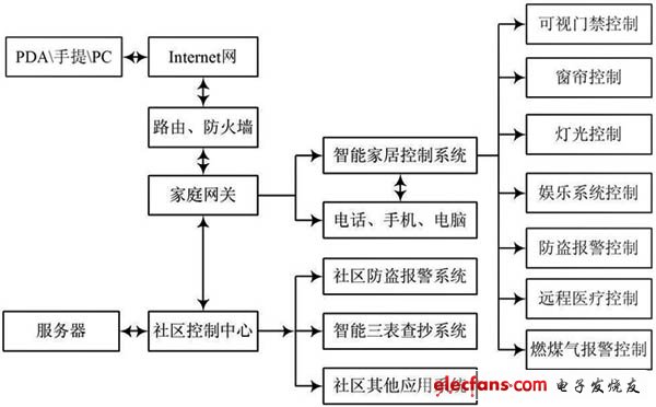
Figure 1 Block diagram of a smart home system
2 System main module design
2.1 Lighting and equipment control
The overall goal of the smart home control system is to establish a comprehensive information service and management system from the family to the community and the entire city by adopting computers, networks, automatic control and integration technologies. Lighting and equipment control in the system can be controlled by intelligent bus switches. This system mainly adopts interactive communication control mode, which is divided into two major modules of master and slave. When the master triggers, the signal is sent through the CPU, after encoding, it is transmitted to the slave module through the bus, and after decoding, the response module is triggered by the CPU. Because the master module is identical to the slave module, the slave module can also perform reverse operations to control the master module to achieve interactive communication. The main block diagram of the system is shown in Figure 2, and the program flowchart of the system's master-slave module is shown in Figure 3. Among them, the host is equivalent to the server of the network, mainly responsible for the coordination of the entire system.
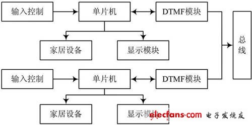
Figure 2 Control block diagram of lighting and home equipment
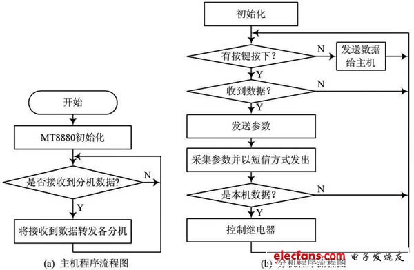
Figure 3 System module program flow chart
For lighting control, different lighting scenarios can be formed to create a comfortable and elegant environment. In order to improve the maintainability and reliability of the system, the system should be designed with intelligent status feedback function, automatic fault alarm function and soft start function. The system can automatically check the load status, check for bad lights, few lights, protection device status, etc .; it can also make intelligent processing based on season, weather, time, personnel activity detection, etc., to achieve energy-saving purposes.
For other home appliances and curtain control, similar to lighting control, both manual and automatic control can be used.
2.2 Design of intelligent security and remote monitoring system
The intelligent security system is mainly composed of various alarm sensors (human body infrared, smoke, combustible gas, etc.) and its detection and processing modules. The intrusion detection alarm circuit is similar to other fire and gas leakage alarm circuits, in which the intrusion detection alarm block diagram and circuit are shown in Figure 4.
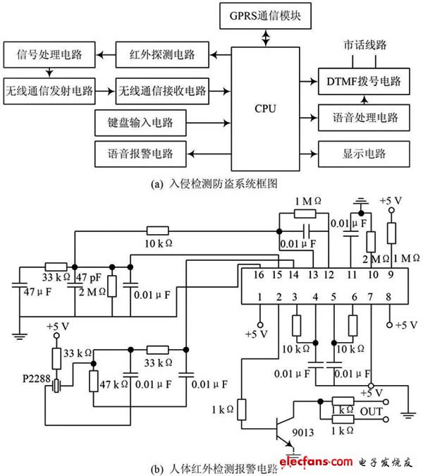
Figure 4 Intrusion detection alarm block diagram and circuit
In Figure 4, the DTMF (dual tone multi-frequency) transceiver circuit is shown in Figure 5 (a). Its core chip is MT8880, which can receive and send all 16 signals of DTMF. It has the functions of receiving call tones and band-pass filtering. The microprocessor is directly connected. The automatic off-hook can control the switch of a relay through the I / O port of the single-chip microcomputer, and the control end of the relay is connected to a resistor and connected to both ends of the telephone line, thereby completing the analog off-hook.
GPRS communication module-TC35 module is mainly connected with the single chip through the serial port to realize the control of the TC35 module by the single chip, so as to realize the remote control function. The circuit is shown in Figure 5 (b).

Figure 5 Interface circuit
It is single signal transmission programmable led pixel strip. Only with One Data wire. the same as WS2811 and SK6812
But It is difference,the WS2812B is just addressable individually, IC just inside on the led.just have DC5V Working Voltage,can be control by extend controller to achieve the flash, movies and so on, Indoor and outdoor is suitable.
It is the most common single control led strips.
RGB LED Tape,WS2812B Rgb LED,WS2812B LED Strip,WS2812B Digital LED Strip
SHEN ZHEN SEL LIGHTING CO.,LTD , https://www.sel-lighting.com