
Today's BCM consists of a large number of solid state switches and fuses. Some BCMs have up to 8-12 battery feeders that provide power for 60-80 loads, and each battery feed is equipped with a fuse, which means that the BCM load (lights, door locks, etc.) is Driven by the drive group, each drive has a fuse. For safety reasons, or simply because the load current is too large to distribute evenly, some loads require a separate fuse. It is said that some BCMs have only one or two fuses. In the event of an output failure, these modules rely on solid state switches to provide "fuse" protection.
This article refers to the address: http://
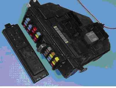
Figure 1. Ford BCM
Fuse
The fuses were passed down from the Krummanu era. Compared to semiconductor components, the fuse is very simple, requires almost no manufacturing process, and is inexpensive... It is because of the simplicity that the fuse is designed as a harness safety device to prevent the harness from becoming an oven cable during a short circuit. 
Figure 2: An early automotive fuse application example (Gary Larson painting)
The working principle of the fuse is a simple relationship between I2R and time. The higher the current, the shorter the blow or open time. The power dissipation of the fuse is proportional to the square of the current through the fuse. When the power consumption is too high, the fuse is blown. This feature also applies to harnesses protected by fuses. When the fuse's "fuse" characteristics are similar to those of the protected harness, the fuse is an ideal choice when the current handling capability is slightly lower. 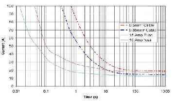
Figure 3: Comparison of I2-t characteristics
Installation location
The question about the fuse protruding from the BCM module is a bit like the three rules of the real estate industry: location, location, or location. If the module has a protruding fuse, the module must be placed in a position that the owner can overhaul. Harness wiring and module orientation, and where the fuses must be placed in the module, is a headache. All of these limitations and protections add to the cost and manufacturing challenges of the module. The Ford BCM shown below installs a flexible board on the CEM3 before placing the fuse on the “edge†of the module. 
Figure 4: Fuse connection port array inside the Ford BCM
Automakers have considerable innovation in finding positions for these BCM modules/fuse units. I saw the BCM module under the dashboard and under the hood and on the footboard (on the right side of the front door hinge), and even saw the BCM module under the rear seat (my car is like this). Some BCMs are hinged and can be pulled out from under the dashboard for easy access. Some BCMs are mounted behind the bezel and can only be found by looking at the user manual (if available). I squatted on the driver's seat more than once, with the foot pressed against the backrest and the head drilled under the dashboard to find the failed fuse.
This is not finished, you have to unravel which fuse number is a riddle for which function... The fuse panel has no mark except for a few lines. Really like a guessing game, you can't tell the player any information except the score. If there is no user manual, BCM is like a food cabinet filled with canned labels. You can only sort and sort, there is no other way. You can only keep guessing until you find a broken fuse number.
Solid state fuses solve many problems
The fuse may blow for no apparent reason. The fault tolerance of the fuse is very poor, even the slightest short circuit will blow (have you ever dropped the coin to the cigarette lighter socket/power outlet?). When you finally find the coin and take it out, the fuse will not reset.
If there is no fuse on the BCM module, the installation location is not the problem. Installing the BCM module under the rear seat does not require drilling under the dashboard to access the BCM module, which is no longer a big problem for me. Because fuses have so much trouble, it's no wonder that automakers are concerned about BCM solutions with fewer fuses or fewer fuses.
A solution that does not allow the car to ignite spontaneously or provide more warranty failures
Therefore, this solution must be reliable and perform well in the application system with virtually no cost.
Today's solid-state switches are self-centered because of the simple form of protection. That is to say, they are more concerned with self-protection than with protecting peripheral components. Solid-state switches have overheating and overload protection circuits that are the best choice when limiting load current due to output shorts. Therefore, replacing a fuse with a solid state switch is sometimes not the best option. 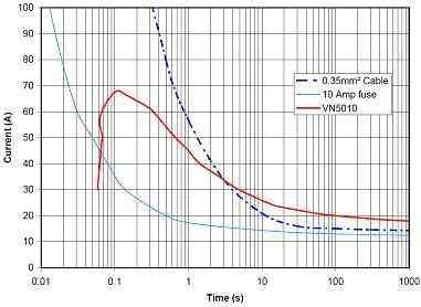
Figure 5: Performance comparison between smart upper arm switch and fuse
Short-circuit events like hard shorts are easier to protect, for example, load currents limited by the drive. In this case, the power consumption is not the result of I2R, but the result of the voltage drop across the driver and the corresponding current limit. This is a high-power event where most of the power is generated on the smart switch instead of the harness. As a result, the temperature of the switch rises rapidly, activating the thermal shutdown function, thereby protecting the associated harness.
Most of the load in the body module is the bulb. The bulb has a very difficult to handle feature: the inrush, we understand and like this feature. The inrush current requires that the current limit of the forced solid state switch be much higher than the current limit value required for steady state switching operation. Everything I said is to illustrate that these high-inrush components allow abnormally high steady-state currents to flow in the harness when no serious hard-circuit events occur. This is where the solid-state switch protects itself without protecting the system. Happening. At this time, the current strength is not enough to activate the switch current limiting function, but it is enough to burn the wiring harness or the board.
In the example of Figure 5 there is a point where the smart switch (VN5010) will continue to move forward and the wire will begin to self-destruct (the red line is above the blue dashed line). If this is true, even the board may self-destruct. Now that the inrush current requirement is likely to be more stringent, we are beginning to realize that it is necessary to develop a protection algorithm that can simulate the characteristics of the fuse.
In applications where multiple "high fuses" are used to protect multiple upper arm drive loads, some issues need to be considered. In these applications, the "big fuse" current handling function may be higher than any of the protected harnesses. Therefore, when a "soft short" occurs on a wire, if the upper arm driver is very robust and can handle higher short-circuit current and fuse protection, the harness or board may self-destruct. 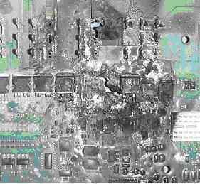
Figure 6: Consequences when the smart switch can only protect itself
The solution is to implement an intelligent circuit protection algorithm that simulates the I2-t characteristics of the fuse. This concept can be transformed into "area under the curve." In the figure below (Fig. 7), the area under the curve (A area) is within the I2-t limit of the protection algorithm. Zone B is a constant overload condition over a period of time in which the overload current is less than the current limit of the smart switch. In this figure, the smart switch is not blocked when the current limit value exceeds the curve. When zone B breaks through zone A, the device is blocked. This principle applies to situations where the overload is present for a long time after the switch is activated. 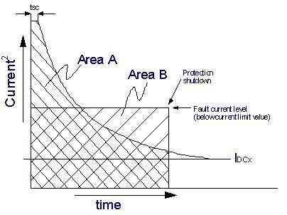
Figure 7: Comparison of overload and power limiting zones
There may be a special transient overcurrent condition: the instantaneous overcurrent exceeds the boundary between the curve and the A zone, but the "area under the curve" is not sufficient to generate the wrong switching condition. In the figure below (Figure 8), this error is very serious, but because the duration is too short, it is not enough to generate the error switch condition. 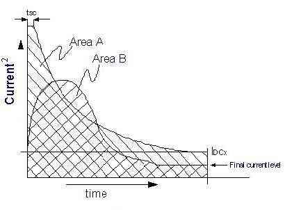
Figure 8: Instantaneous errors do not produce an error shutdown condition
This protection algorithm allows for excellent multiple inrush currents without forcing the system to handle much higher steady-state currents than normal. Therefore, this algorithm provides a robust protection function that protects both the switch itself and the harness that is driven by the switch. Coupled with other security mechanisms such as built-in watchdog and activation, this already secure solution will become more secure.
This algorithm can be implemented on a chip using a lifting sequence counter that controls the square of the current flowing through the switch (Figure 9). 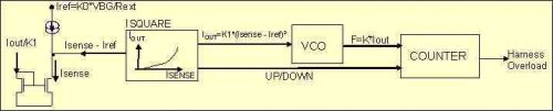
Figure 9: it limits the control loop
The direction of the counter is determined by the reference current. When the sense current is higher than the reference current threshold, the counter counts in ascending order, and the rate is proportional to the square of the difference between the sense current and the reference current. When the sense current is below the reference current threshold, the counter counts in a descending order of fixed values. The purpose of the fixed descending count value is to better estimate the heat dissipation of the fuse.
This threshold inrush current is slightly lower than the current handling capability of the wire (as shown in Figure 5, less than 14A DC). Once the counter reaches a certain preset value, the output is immediately turned off. Because this algorithm protects the wires with the characteristics of a fuse type, the drive remains off until the microcontroller is reinitialized and the output is turned back on. 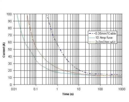
Figure 10: Extrapolation of the i2-t curve with the protection algorithm compared to wires and fuses
The application of the intelligent switch series that implements this protection method reduces the wiring harness cost of a given body electronic module, limits the number of fuses, and improves reliability and safety.
When a short circuit output eventually burned her BCM, the compartment was filled with a pungent burnt smell, as shown in the circuit board of Figure 6.
DIN Electric Bell
Low Voltage Electrical,Electric Bell,Patent Intermittent Electric Bell
Wenzhou Korlen Electric Appliances Co., Ltd. , http://www.korlenelectric.com