
1 Introduction
The voice system is an indispensable part of the elevator, used for floor reporting, direction reminders, warnings, fire-fighting intercoms, and advertising. Most of the traditional voice systems use voice devices to store and play voices, but there are defects such as complex external circuits , poor sound quality, high cost, small capacity, and difficulty in changing voice. In view of this, an elevator voice system based on CPLD and VS1011E decoder was designed.
2 System Overview
The basic function of the elevator control system is to display the floor number according to the user's floor button information and broadcast the arrival floor voice. The block diagram of the elevator voice system is shown in Figure 1.
This article refers to the address: http://

2.1 Information input
The input information is divided into two parts. One is that the user sends a floor request to the system through a button, and the other is that the elevator control system arrives or cancels the notification according to the floor.
2.2 processor
The floor system is controlled according to user information and control system information, and the control is divided into two parts: display floor and voice report. The system requires the processor to process quickly and have a large memory buffer space.
2.3 display module
Used to display the number of floors and tips for overloading, fire and emergency situations, and even the release of information such as date advertisements. The low-rise building elevator system generally uses LED display, which is a dot matrix display. With the development and maturity of liquid crystal display control technology, high-end building elevator systems use LCD display.
2.4 logic device
Mainly CPLDs that can perform powerful data processing quickly. As can be seen from the entire system, the processor needs to respond to the input information and can drive the display module to work, and also read and write operations on the extended memory, and send the voice data of the memory to the MP3 decoder for decoding. These all pose great challenges to the processor. If the performance of the processor is low, the whole system may be disordered. Therefore, the processor must be "burdened".
Based on the above considerations, the system uses CPLD. For the control of the MP3 decoder, the processor is only responsible for sending control commands, and the specific operation is done by the CPLD. This greatly increases the speed and reliability of the system.
2.5 memory
Used to store large amounts of voice data. There are three types of memory for MP3 players on the market: magnetic storage (2.5-inch hard drives), optical storage (CD-ROM and DVD), and Flash. Among them, Flash memory can also be divided into NAND Flash, CF card, SD card, SMC card MMC card and SONY memory stick. Taking into account the convenience of system design and use, the system uses NAND Flash.
2.6 MP3 decoder, DAC and amplifier
As the core of the MP3 player, the MP3 decoder is responsible for converting the MP3 format data encoded by the microprocessor from the memory into a digital audio signal and transmitting it to the DAC; the DAC converts the digital audio signal into an analog signal, and finally the analog audio signal is passed through the earphone or The amplifier emits a sound.
3 hardware design
3.1 System working principle
According to the read and write rules of Flash and the decoding protocol of MP3, the logic rules of the CPLD are preset. The controller issues control commands and transmits data to the CPLD based on the input information. The CPLD reads and writes Flash according to the logic rules according to the received command and sets the internal control register and transmits the audio data to the MP3. The analog signal output by the MP3 decoder directly drives the earphone. To drive the high-power speaker, an external power amplifier is required. Its system hardware circuit is shown in Figure 2.

3.2 Microcontroller STC89C58RD+C
STC89C58RD+C is a new generation of 51 enhanced high-performance single-chip microcomputer with strong encryption, super anti-interference, ultra-low power consumption, programmable in the system, and can be supplied with internal MAX810 dedicated reset circuit.
The STC89C58RD+C uses the MCS51 core and is pin compatible with the AT89S52. It should be noted that the D-type internal integrated reset circuit, the reset pin is directly grounded. It has 32 KB of Flash and 16 KB of EEPROM and contains 1 280 bytes of SRAM memory. Therefore, the STC89C58RD+C can meet system control requirements.
D0~D7 communicate with CPLD to realize data transmission and command control. Eight ports need pull-up resistors with a resistance of 10 kΩ. The pull-up resistors need 3.3 V power supply to match the CPLD power supply. DREQ1 (P3.2) is connected to the CPLD to read the busy status of the MP3 decoder. READY (P2.3) is connected to the CPLD to determine if the flash is ready. WR, RD, and ALE are connected to the CPLD for read and write selection and timing control of the Flash.
3.3 CPLD circuit
CPLD is the intermediary between the microcontroller, Flash and MP3, responsible for logic control and data transfer. The CPLD circuit uses Xilinx's XC9572-VQ64. The XC9572-VQ64 features 72 macrocells, 1 600 available gates, 52 I/O ports, power supply as low as 2.5 V, and online programming. J1 is used for ISP downloads. The crystal oscillator is 40 MHz.
3.4 MP3 decoder VS1011E and circuit design
The VS1011E audio decoder is the third generation of the VS10xx series and is a single-chip MP3/WMA/MIDI decoding and ADPCM encoder. It integrates high-performance, low-power DSP processing core (VSDSP), 5.5 KB of on-chip RAM for users to store code and data, serial SPI bus interface, and two-channel high-quality sampling frequency adjustable 16-bit DAC. The VSl011E operates from a 12.288 MHz to 14 MHz or 24.576 MHz to 28 MHz clock range and can decode MPEG1&2 Laver 1, 2, 3 and MPEG 2.5 Layer 3 formats, WAV formats and PCM format files.
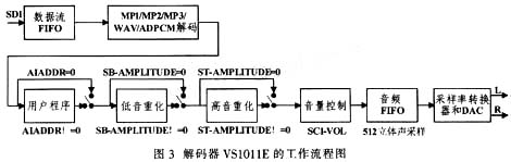
The workflow of VS1011E is shown in Figure 3. The workflow of VS1011E is as follows: First, MP3 or WAV format audio files enter the chip through the SDI bus and are decoded. After decoding, if SCL_AIADDR!=0, the application area code will be executed and the code address will be provided by the corresponding address register. Then, according to the settings of the SCL_BASS register (SB_AMPLITUDE bit and ST_AMPLITUDE bit), the data may be sent to the bass and treble optimizer for sound processing. Thereafter, the data is passed through the volume control unit and backed up to the audio FIFO. The audio FIFO holds the data and acts as an input to the sample rate converter and DAC. The sample rate converter converts all of the different sample rates into CLKI/512 for delivery to the DAC. The DAC sequentially produces stereo analog signals in bits, which are then sent to the headphone power amplifier.
Since the system is an elevator system, to promote the sound of high-powered speakers, an external power amplifier is required. The power amplifier adopts CD4752CZ. The power amplifier has a large voltage range and anti-interference ability, and is suitable for an elevator working environment with large voltage fluctuation and strong external interference.
3.5 Flash memory
Samsung's NAND Flash K9F5608 is used as the memory. The K9F5608 has 32 MB of space and is fully compliant with the elevator voice system.
NAND Flash uses blocks and pages as storage units. K9F5608 includes 2 048 blocks, each block includes 32 pages, and the page size is 528 bytes. It is divided into two 256-byte data areas and the last 16-byte spare space.
The K9F5608's read, write, and erase operations are all done by commands. The read/write operation is performed in units of pages. The erase operation is in block units, cannot be byte erased, and needs to erase a whole block before each rewrite operation; each block has a limited number of erasures of about 100,000 times, and the data is saved for more than 10 years. . A typical read operation time is 50 ns/word, a write operation time is 200 μs/page, and an erase operation time is 2 ms/block.
4 software design
4.1 main flow chart
During the operation of the elevator, if there is no button, the elevator voice system will automatically broadcast advertisements, weather forecasts and other information, accompanied by a bit of matrix or liquid crystal display. When a button is pressed, the voice system calls the corresponding button voice processing program according to the button value. The main program flow chart is shown in Figure 4.

4.2 Software Design of YS1011E
The software design uses VS1011E audio decoder, and its control flow is shown in Figure 5.
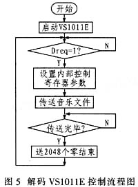
The following points should be noted when controlling the MP3 decoder:
Set the parameters of the internal control register MODE. Includes support file format, soft start settings, data stream mode settings, DCLK trigger edge settings, and SDI data first bit settings;
If the clock rate is not 24.576 MHz, then the SCI_CLOCKF register needs to be set. If the SCI_CLOCKF multiplier clock is changed, the appropriate sampling rate should be written to the SCI_AUDATA register, waiting for at least 11 000 clocks before SPI communication;
Set the volume register SCI_VOL, 0 is the maximum volume, 0xFEFE is muted, 0xFFFF triggers the analog power-on mode;
To strengthen the bass and treble, set the register SCI_BASS;
Using the user code, SCI_AIADDR is set to zero;
Using RAM-level user code, activating SCI_WRAM, SCI_WRAMADDR, and SCI_AIADDR load data enables the required functionality.
5 Conclusion
The system has been put into the market with good sound quality and stable functions. Voice systems based on CPLD and VS1011E decoders are now used in many applications, such as bus station name broadcast systems.
Coaxial Cable ,Pigtail Coaxial Cable,Aerial Fiber Optic Cable
Shenzhen Hongyan Wire Industry Co., Ltd. , http://www.hy-cable.com