
The principle and workflow of the electric power steering system (EPS) are analyzed in detail. The pic18f458 single-chip microcomputer is used as the controller, and the enhanced PWM PWM pulse width modulation module ECCP controls the assist motor to realize the power assist control, return control and damping of the eps system. Control and other methods.
The application software adopts the OSEK OS embedded operating system as the platform, and the eps system is divided into multiple tasks, and the priority scheduling is used to achieve the purpose of coordinated operation of the system.
With the development of electronic technology and motor control technology, the research of the Electric Power Steering (EPS) system has made great progress. At present, automotive electric power steering has partially replaced the traditional Hydraulic Power Steering (HPS).
After more than 20 years of development, eps technology has become more and more perfect, and has achieved considerable results, and has been widely used in light cars and vans. Traditional software design is not easy to maintain, portability is poor, and real-time performance is not guaranteed. With the continuous development of the automotive industry, electronic technology is getting more and more applications in automobiles.
In order to meet the needs of the increasingly complex development of automotive electronic control software, to achieve the portability of application software and compatibility between control modules of different manufacturers, in 1993 the German automotive industry jointly launched the "open system and interface of automotive electronics." The software specification, OSEK (open systems and the corresponding interfaces for automoTIve electronics), is intended to provide an open-ended industry standard for distributed control units on automobiles. In 1994, the automotive distributed operating system VDX (Vehicle Distributed ExecuTIve) and the OSEK specification used by the French automotive industry merged to form the OSEK/VDX specification.
The specification has now become an ISO international standard (ISO17356). Based on this, this paper proposes an eps software design method based on embedded real-time operating system.
1 eps system structure and working principle
1.1 EPS system structure
According to the motor installation position, eps can be divided into steering shaft assist type, pinion assist type and rack assist type. Figure 1 is a schematic illustration of a typical electric power steering system. The main components of the eps control system:
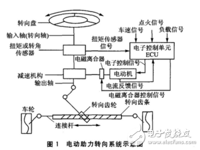
1 Torque signal sensor measures the magnitude and direction of the torque that the driver acts on the steering wheel.
2 Vehicle speed signal sensor, measuring the driving speed of the car, will provide different power in different speeds and steering wheel torque to ensure the EPS system is flexible at low speed and has a good "road feeling" at high speed.
3 Power-assisted motor is one of the most critical components of EPS system. The power-assisted motor requires low speed, large torque, small moment of inertia, high reliability, low vibration, low noise, small size and light weight. Figure 1 Schematic diagram of electric power steering system
4 Electromagnetic clutch, mainly plays the role of safety protection. When the eps fails, the electromagnetic clutch will cut off the connection between the motor and the steering column in time, and the car works with the traditional mechanical steering device to ensure the safety of driving.
5 The speed reduction mechanism is an indispensable part of the eps system, which is used to generate the effect of deceleration and twisting.
6 Electronic control unit ECU, mainly including information processing unit and its peripheral circuits. It is the control core of the eps system. The control unit issues commands to control the motor operation based on the signals of the steering wheel torque sensor and the vehicle speed sensor after A/D conversion and logic analysis and calculation.
1.2 EPS system works
Although there are 3 types of eps, the working principle is the same: through the torque sensor and the vehicle speed sensor, the signal is collected, and the signal is sent to the electronic control unit (ECU) through A/D conversion. The single chip is based on the collected speed. Signal and torque signals, and real-time control of the DC servo motor according to the corresponding control strategy.
According to the different requirements of the car's steering, eps is controlled according to different control methods, usually there are three basic control methods.
(1) Assisting the control of the car to drive in the low speed range, the electric control unit performs the normal control of the motor when the steering wheel is turned and leaves the intermediate position; the current of the assist motor is determined by calculation to obtain the appropriate assist torque, making the steering operation light and sensitive .
(2) Correction control The positive control can improve the return performance of the car. When the car is driving in the low speed range and the steering wheel is returned to the middle position, the electric control unit makes the motor current decrease rapidly, so that the steering wheel can be quickly corrected. At high speed, the damping control is used to short-circuit both ends of the motor, generating and returning. The positive positive torque is reversed, which improves the positive overshoot of the steering wheel.
(3) Damping control Damping control can attenuate the steering wheel shake phenomenon that occurs when the car is driving at high speed, and eliminate the shimmy caused by the steering wheel input due to the road surface. The principle is very simple, that is, when the car is at high speed, the motor is short-circuited, its terminal voltage becomes zero, the motor will not provide power, but due to the induced electromotive force, the motor will generate a torque opposite to its direction of rotation.
This process is equivalent to increasing the damping of the steering system, and the driver can get the proper road feel without feeling floating.
2 eps control system ECU design
The main function realized by the eps system is to collect the torque sensor signal, the vehicle speed sensor signal and the motor feedback current signal. Through the control strategy and control algorithm in the controller, the servo motor is controlled by the pulse width modulation to provide the steering assist force to the driver.
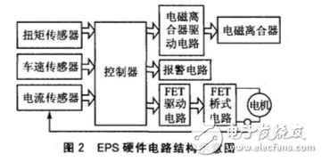
In addition, considering the particularity of its application objects and the absolute status of its security requirements, the system also needs to provide many emergency treatment solutions. The hardware design of the eps system mainly includes the following main modules: controller core system design, control unit interface circuit, motor drive and its protection circuit, electromagnetic clutch control circuit, sensor signal processing circuit and power system circuit design, etc. Shown. Here we mainly introduce the controller and motor drive circuit.
2.1 The microcontroller of the controller eps system uses Microchip's pic18f458 chip. This series of chips has the following properties:
1 16-bit wide instruction, 8-bit wide data channel, 2 MB of program memory, 4 KB of data memory, up to 10 MIPS of execution speed.
2 40 MHz clock input, 4 to 10 MHz with PLL phase-locked loop active crystal/clock input.
3 Priority interrupts and 8&TImes; 8 single-cycle hardware multipliers.
4 Capture/Compare/Pulse Width Modulation (CCP) Module: ◆ Capture Input – 16 bits with a maximum resolution of 6.25 ns; ◆ Compare Unit – 16 bits with a maximum resolution of 100 ns; ◆ Pulse Width Modulation (PWM) Output - resolution is 1 to 10 bits; ◆ highest PWM frequency - frequency is 156 kHz for 8 bits and 39 kHz for 10 bits.
5 Enhanced CCP module has the above CCP features, but also has 1, 2, 4 PWM output, selectable PWM polarity, programmable PWM dead time.
6 10-bit, 8-channel A/D conversion.
7 CAN bus module.
2.2 drive circuit design
The design of the motor control circuit is a relatively important part in the design of the electric power steering system. With the computer entering the control field and the emergence of new power electronic power components, the structure and control method of the DC motor have undergone great changes. Pulse-width modulation (Pulse Width ModulaTIon) is implemented using a fully-controlled switching power component. , PWM) control has become the absolute mainstream. In this system, the control of the motor is the PWM pulse width modulation control method. The full bridge bipolar drive circuit is shown in Figure 3.
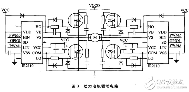
The ECCP pin of the pic18f458 microcontroller is connected to two driver ICs IR2110 (each IR2110 can control two MOSFETs) to control the turn-on and turn-off of the four MOSFETs to control the booster motor. The eps system needs to implement three control modes: regular control, positive control, and damping control.
3 eps software design
With the further complication of embedded applications and the improvement of real-time and reliability requirements, in order to properly schedule multiple tasks and utilize system resources, embedded software design based on embedded real-time operating system has gradually become an embedded system design and development. Mainstream. There are hundreds of embedded real-time operating systems, each with its own characteristics. The open source embedded real-time operating system has unique advantages in cost and technology, and has an increasingly important position.
This paper chooses the open source embedded real-time operating system PICOS18 as the software development platform for eps.
PICOS18 is a real-time operating system implemented in accordance with the OSEK/VDX standard. PICOS18 is a multi-tasking deprived micro-real-time kernel, very small, occupying less than 1 KB of program space (ROM), only 7 B of data space (RAM), and very little ROM and RAM required for system code capacity and operation. Provides functions such as task management, timer management, event management, and interrupt management; task scheduling based on priority, with 16 priorities, 1 system occupied, users can create 15 tasks, each task can also have at most 8 events.
3.1 Application Software Development
The embedded real-time operating system transforms function-oriented application development into task-oriented application development. Therefore, the process of software development is to subdivide the application system into multiple tasks according to functions, then implement each task and determine the appropriate priority for the task. Level; for operations with high real-time requirements, you need to write the relevant interrupt service program. According to the working principle of eps, it can be divided into 8 tasks.
(1) Task1 - Vehicle speed signal acquisition and expansion task, used to calculate the speed of the vehicle. Task1 is in a wait state after power-on, waiting for the vehicle speed calculation event EventSpeed. Use the timer/counter TMR0 module to generate an interrupt when the counter overflows (after the number of speed signal pulses), enter the speed interrupt service routine, record the total pulse period time, then set the event EventSpeed ​​to activate Task1. At this time, Task1 is in the ready state. Under the management of the operating system scheduling mechanism (complete preemptive), when the task with priority higher than Task1 in the ready queue runs, Task1 runs, according to the recorded pulse time and number of pulses. , calculate the speed of the car and filter it. After execution, Task2 is activated, event EventSpeed ​​is cleared, and Task1 is in a wait state.
(2) Task2 - the basic task of torque signal acquisition, used to collect torque signals. This task is activated by Task1 and executes at the same frequency as Task1. Because the vehicle speed signal and the torque signal are the two most important parameters of the EPS system, these two parameters must be updated in time to ensure that the selection of the assist mode and the determination of the assist size are timely and accurately controlled.
(3) Task3 - the basic task of current feedback signal acquisition, used to collect motor feedback current. This task is activated by Task5 and is only activated when the system is under boost control. The difference between the parameter and the target current is controlled by the PID regulator, so that the motor can quickly provide the corresponding torque to achieve the purpose of assisting.
(4) Task4 - Fault diagnosis extended task for fault monitoring and diagnosis. After power-on operation, wait for the message MsgSpeedErr to determine that the vehicle speed is normal; wait for the message MsgVoltErr to determine that the voltage is normal; wait for the message MsgTorqueErr to determine that the torque is normal. In the event of a fault, the task will immediately disconnect the relay, causing the steering system to be in a mechanical steering state to avoid an accident.
(5) Task5 - The assist mode selects the basic task for selecting the boost mode and determining the target current under the boost control mode. This task is activated by Task2. The assist mode is judged by the speed and torque, and the target current is obtained by the assist characteristic curve under the assist control. The number of executions of this task is the same as that of Task1 and Task2 to ensure that the power assist mode and booster size are real-time and accurate.
(6) Task6 - power control basic task, power control, activated by Task3. The target current obtained by Task5 and the feedback current of Task3 motor are closed-loop controlled by PID regulator, and finally the power-assisted motor is controlled by PWM pulse width modulation.
(7) Task7 - back to control the basic tasks, back to control, activated by Task5. When the vehicle speed is very high, the motor is short-circuited at both ends, which produces positive damping and reduces back-to-back overshoot; when the car is at low speed, the motor is quickly disconnected at both ends, reducing the motor resistance and making the steering quickly return.
(8) Task8 - Damping control basic task, damping control, activated by Task5. Damping control is used for various states at high speeds (return, steering, and straight travel). When back, the damping control can reduce the system overshoot; when turning, it can increase the resistance, so that the driver can get a better road feeling; when driving straight, the impact of the road on the steering wheel can be reduced.
3.2 Task priority
PICOS18 adopts the preemptive scheduling method, that is, all tasks are preemptive, each task has a certain unique priority, and the more important the task, the higher the priority. Since the assist control (Task6) task must be run at the right time, the Task6 has the highest priority, the return control (Task7) and the damping control (Task8) are the second, followed by the fault diagnosis task (Task4), and the rest of the tasks are according to their priorities. The execution order of the activation is determined. Task4 is in a wait state when it starts running. If no abnormal signal is detected, it is no longer executed. After executing a loop in sequence, Task1, Task2, and Task5 continue to respond to the speed interrupt and re-execute. This scheduling method not only collects the latest vehicle speed signals and torque signals, but also enables the eps system to provide real-time and accurate assistance, and also improves CPU utilization and makes full use of hardware resources.
3.3 Task Configuration (OIL)
PICOS18 defines various parameters of the task through taskdesc.c and is \[5\] written with OIL (the implementation language of OSEK/VDX, similar to a C structure definition) in the OSEK/VDX specification. Since PICOS18 does not provide a GUI for task configuration, it can only be written step by step. The parameter definition structure of the task is as follows:
Rom_desc_tsk rom_desc_task={
TASK_PRIO, /* priority of the task * /
Stack, /* stack address (16 bit) * /
TASK, /* starting address (16 digits)*/
READY, /* Status at initialization*/
TASK_ID, /* task ID*/
Sizeof(stack)/* stack size (16 bits)*/
};
AlarmObject Alarm_list\[\] = {
/****** The first task **********/
{
OFF, /* status*/
0, /* alarm value */
0, / * cycle * /
&Counter_kernel, /* counter associated with the alarm */
TASK1_ID, /* task ID*/ to be activated
ALARM_EVENT, /* passed event */
0/* callback*/
},
.../*Other tasks*/
};
Resource Resource_list\[\] = {
{
10, /* priority*/
0, /* task priority * /
0, /* is locked, 0 means not locked */
}
};
Counter Counter_list\[\] = {
/****** The first counter******/
{
{
200, / * maximum count allowed * /
10, / * prescaler * /
100/* minimum period*/
},
0, / * count value * /
0
}
.../*other counters*/
};
4 ConclusionThis paper analyzes the structure, working principle and three control methods of the eps system. The motor is controlled by the ECCP module of the pic18f458 microcontroller, which realizes the power system of the eps system under various conditions. The embedded real-time operating system not only improves the CPU utilization, but also ensures the real-time requirements of the eps system, and also improves the stability, reliability and portability of the system operation. OSEK/VDX is an international standard for automotive electronics development. Real-time systems developed using the OSEK/VDX specification can improve the efficiency of software module migration, reuse of software modules, and communication between different electronic control units. The development of automotive electronic control units with OSEK/VDX has become a trend.
APM SP300VAC3000W is an economically programmable DC and AC output power supply to provide reliable voltage and simulation for general applications such as testing for commercial, power electronics, avionics, military and IEC regulation test applications. The AC power source has various communication interface and can be remote controlled by computer.
The AC source is capable of delivering up to 6 times of peak current compared to its maximum rated current that makes it ideal for inrush current test.
Some features as below:
- 5.6"large touch color screen
- AC+DC mixed or independent output mode
- Capable of setting output slope/phase angle
- Built-in IEC standard test function
- Built-in multiple protections
- Built-in power meter
- Support impedance function
- Support for LIST/PULSE/STEP mode & Transient mode
- Standard RS232/RS485/USB/LAN, Optional GPIB/multiphase card.
- Support master and slave parallel mode to realize power extension
- Support harmonics/inter-harmonics simulation and measuring function
- Support for USB data import/export and scree nap from front panel
- PWM technologies, with up to 86% efficiency
- CE, CSA, UL, ROHS Certified
3000W AC Power Supply,Programmable AC Power Supply,Adjustable Ac Dc Power Supply,3000W Switching Power Supply
APM Technologies Ltd , https://www.apmpowersupply.com