
Over the past 20 years, CareFusion Nicolet has been a pioneer in the development of EEG diagnostic systems. By leveraging ADI's extensive line of amplifiers, CareFusion is able to optimize its analog front end to meet today's EEG design challenges.
This article refers to the address: http://
Although this article covers only one EEG application, most of the theories will also be helpful to ECG design engineers. As many EEG and ECG device designers know, the difference in half-cell potential in the electrode can cause large dc offsets, and the measurement system must be able to tolerate this offset. CareFusion's existing system design can handle offsets up to ±900mV. In order to cope with the different electrode types and environmental conditions in the field, CareFusion hopes to increase the tolerance to ±1300mV. At the same time, they are considering the possibility of battery-powered design, so they need to significantly reduce power consumption, including instrumentation amplifiers. The existing power consumption is 28mW per channel, and the designer hopes to reduce it to less than 10mW. For ECG and EEG front-end designs, designers face trade-offs between noise, offset processing power, and power consumption.
Most instrumentation amplifiers have a large amount of noise due to the subtractor stage. In high-gain applications, this has little effect because the noise remains constant at the output, independent of gain. However, in EEG and ECG applications, the gain is limited by the large offset from the electrodes. Therefore, if you want to use large gains for good noise performance, the offset requirements will force the design to use a large power supply.
This is what CareFusion has taken in its previous design with the AD8221 instrumentation amplifier. The output noise of the AD8221 is 75nV/√Hz and the input noise is 8nV/√Hz. To reduce the impact of large amounts of output noise on the input, they set the AD8221 to a gain of 14.8. This gain also increases common-mode rejection by 23dB because the common-mode gain is 1. However, in order to handle 900mV electrode offset with a gain of 14.8, a 115.5V DC power rail must be used. The EEG amplifier consists of 64 such channels, which consume too much power for battery-powered applications.
For this application, what is really ideal is a low-power instrumentation amplifier with low output noise, but this is not easy. The output noise of the instrumentation amplifier is mainly determined by six resistors (R1 to R6 in Figure 1). One possible solution is to lower the value of these resistors, but there are several disadvantages:
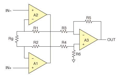
Figure 1. Standard instrumentation amplifier configuration.
1. The internal instrumentation amplifier must drive more current to these resistors. In order to maintain good linearity under such higher driving conditions, it is necessary to construct an amplifier with a higher output driving capability, which requires designing a higher power amplifier. On the other hand, a larger current will flow through the small value resistor.
2. The Rg gain setting resistor will become smaller, which is a good thing in terms of noise, but it is not good enough under large differential overvoltage conditions. It can degrade the performance of the large differential voltage in the high gain configuration of the amplifier input. Instrumentation amplifier designers can respond by adding circuits, but this circuit increases input noise.
3. As the resistance in the EEG device subtractor circuit becomes smaller, the input impedance of the instrumentation amplifier will also become smaller. This means that if the system designer wants to drive this pin with a buffer (common in EEG applications), the driver amplifier must have a very low output impedance over the target frequency range.
CareFusion decided to use higher noise for lower power consumption. As a result, they began looking for alternatives to the AD8221 – lower power consumption but still meeting other performance requirements. One of the instrumentation amplifiers they considered was the AD8235/36, which has very low power consumption and small size, but the noise is too high, and the maximum supply rail is 5V, which cannot meet the DC offset requirements.
Another device considered by CareFusion is the AD627, which consumes very little power and supports wide power rails. It has good performance relative to power consumption. However, it uses a SOIC package that is large in size and is not conducive to reducing the size of the board. Analog Devices also has a wide range of devices from 300μA to 500μA supply current and wide supply range, but all of these devices have an input bias current of at least 20nA, which exceeds the 5nA rating of the CareFusion design. After discovering that ADI and other vendors did not have any instrumentation amplifiers to meet the requirements, CareFusion decided to build it on its own. They know that in order to achieve a CMRR of more than 100 dB, the resistance in the subtractor stage must match. They have tried matching resistor networks in the past, but such networks are very expensive and seem to have never achieved the desired CMRR performance. They quickly discovered that the AD8278 differential amplifier had the performance and power they needed. Traditional four-resistor differential amplifiers are more complicated than they seem. For an ideal op amp, the CMRR is limited by the resistor match (R3-R6 in Figure 1). The approximate calculation formula of the differential amplifier CMRR is as follows:
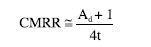
Ad is the gain of the differential amplifier and t is the tolerance of the resistor. Thus, for 1x gain and 1% resistance, CMRR = 50V/V or approximately 34dB; for 0.1% resistance, CMRR = 500V/V or approximately 54dB. The above formula applies to low frequency situations. When the frequency is high, the CMRR may fall further. For example, if the input capacitance difference of the two op amps is 400fF~500fF and the resistance is 10kΩ due to PCB layout or internal chip layout, the AC CMRR at 10kHz will drop by 6dB~7dB. This can be important if there is a 20 kHz (or higher) switching regulator in the system. Even with ideal resistors and balanced capacitors, CMRR is ultimately limited by op amps.
The performance of the differential amplifier is mainly divided into two categories. First, typical high-side current sensing applications require 3% to 5% accuracy at the high end of the current range. A low cost op amp with reasonable offset and 1% resistance can achieve this. Keep in mind that some low-cost op amps may have a CMRR of less than 50dB, which is often overlooked. Second, more sophisticated applications, typically as the second stage of discrete instrumentation amplifiers, range from 0.1% to 1% with CMRRs in excess of 70dB to 80dB. This can be achieved with a good op amp, four matching resistors with low temperature coefficient (TC), and a careful PCB layout. Considering the total cost of discrete solutions and board space, single-chip differential amplifiers appear to be very attractive. This is why CareFusion chose the AD8278. They configured their gain to 1/2, which allowed them to increase the gain of the input buffer, lower the power rail (finalized to ±7.5 VDC), and meet noise and dc offset tolerance requirements. The gain of the AD8278 can be configured as 1/2 or 2. Although CareFusion is facing low-noise applications, they still choose to configure the gain of the AD8278 to 1/2. It is generally believed that placing the amplifier at the highest gain stage results in the best noise performance. However, since the AD8278 is the second stage of the design, placing the amplifier at a lower gain stage actually helps to improve the noise performance of the design. This will allow more gain to be applied in the first stage. An important rule of low noise design is to have as much gain as possible in the first stage, and this design is no exception. Placing more gain in the first stage also helps improve the CMRR performance of the instrumentation amplifier. We can calculate from the previous discussion of the relationship between resistance tolerance and CMRR. When the gain of the differential amplifier is changed from 1/2 to 2, the CMRR will increase by 6dB. However, if we provide an additional 4x gain in the first stage, the differential gain will be increased by a factor of 4, but the common mode gain remains the same. In other words, with the first stage of amplification, we can get an additional CMRR of 12dB, and when applying the gain to the differential amplifier, we can only get a 6dB improvement. Note that this technique only applies if the op amp in the first stage has a good CMRR, so it is important to use a high quality op amp. Using a G=1/2 differential amplifier stage is one of CareFusion's optimized discrete designs compared to integrated instrumentation amplifiers. In general, an integrated instrumentation amplifier must set the internal differential amplifier's gain to 1 or higher because the lower differential amplifier gain limits the ability of the instrumentation amplifier to handle wide common-mode voltage swings. After extensive searching, CareFusion chose the AD8622 as an input buffer op amp. The op amp has all the features they need: small package size, low power consumption, low input bias current, low 0.1Hz~10Hz noise and wide power rail. Another important feature is unity gain stability. Although the op amp operates at 10x gain, in an instrumentation amplifier configuration, the common mode signal sees a gain of 1, which can cause stability problems.
CareFusion divides the system in a way that is unique. Sometimes, three parts of a four-channel op amp are used to build an instrumentation amplifier, which is a trap that can easily fall into.
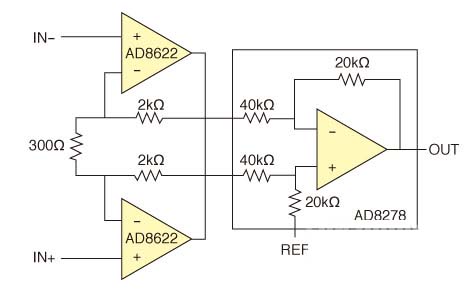
Figure 2, a schematic diagram of the CareFusion instrumentation amplifier.
According to Vos, TCVos, gain, bandwidth, CMRR, etc., the requirements of the first stage are completely different from those of the differential amplifier stage. To get the last 10% performance, the first stage uses a two-channel amplifier and the second stage uses a single-channel amplifier. In order to achieve low voltage noise in an op amp, the input stage needs to consume a large amount of current that is not needed in the second stage. If the second stage drives a heavy load, then more drivers are needed than the first stage op amp. Another disadvantage of four-channel amplifiers is that the heat from the output op amp may be fed back to the first stage of other op amps in the same package.
CareFusion's first choice was to use an integrated instrumentation amplifier to save board space. However, the use of precision differential amplifiers allows them to fine tune the instrumentation amplifier without the need for an expensive resistor network that occupies board space. They are able to significantly reduce power consumption while still maintaining important performance characteristics such as noise, CMRR, and DC input tolerances (Figure 2).
The China Blue Sport Bluetooth Earphone is wear comfortable, sweat-proof headphones. True wireless design is more convenient in running, gym, walking.... Also long work time, even with portable charging case, give you longer music experience.
Blue Sport Bluetooth Earphone,Sports Headphones,Earbuds For Running,Bluetooth Headphones With Mic
ShenDaDian(China) Digital Electronics Co.,Ltd , http://www.btearbuds.com