
The stable classification has not been unified until now. There are many different in Europe and America, and there are traditional classifications as well as current classifications. Let me sort out according to my own ideas.
The stability of the power system is divided into three types of power stability: voltage stability, frequency stability, and power angle stability.
The stability of the power angle is divided into three types: static stability, transient stability, and dynamic stability.
Among them, static stability is the stability of the system after the system is disturbed by small disturbance; transient stability is the stability of the system after the large disturbance in the subsequent 1-2 cycles; dynamic stability is after the small disturbance or after the large disturbance 1-2 weeks And the stability after taking technical measures.
The above three stability concepts use a ball placed in a bowl to describe whether the ball returns to its original position after being subjected to external action:
Put a ball in a bowl. When the ball receives a small force from the outside, it will deviate from its original position. If the bowl is very short and short like a plate, the ball may fall from the bowl. We will say This system is not stable enough. In fact, small disturbances in the power system are constantly occurring, and the balls in the bowl are constantly rolling at the bottom of the bowl. The higher the height of the bowl, the greater the static stability limit of the system and the more stable the system.
When the ball in the bowl is subjected to a large external force, whether the ball is still in the bowl is the transient stability problem of the system. The most important measure to improve the transient stability of the system is rapid relay protection. The role of the relay is equivalent to reducing the time of action of this external force. The faster the relay is, the shorter the external force will be, and the ball will not fall down at once. The automatic voltage regulator acts at this time to automatically change the slope of the bowl. When the ball rises, the slope is increased. When it is lowered, the slope is reduced, so that the ball rolls rapidly in the bowl.
If the friction between the bowl and the ball is small, the ball will be rolled back and forth in the bowl after being disturbed. Especially if the external force of the disturbance is constantly applied back and forth, for example, we are constantly swinging, this ball We will never stop rolling back and forth or even fall, we say that the dynamic stability of this system is poor. The frictional resistance here is equivalent to the damping of the power system, and the external force applied continuously back and forth is equivalent to the negative damping generated by the automatic voltage regulator. In general, automatic voltage regulators play a detrimental role in the dynamic stabilization of the power system, producing negative damping, reducing the overall system damping. When we add a PSS device to the automatic voltage regulator, the PSS turns the negative damping generated by the automatic voltage regulator into positive damping, which is equivalent to increasing the friction coefficient of the bowl and the ball, so that the rolling amplitude of the ball is rapidly reduced, so The dynamic stability of this system meets the requirements.
The "Guidelines for the Safety and Stability of Power Systems" stipulates that the standards for China's power system to withstand large disturbances are divided into three levels:
The first level of standard: maintaining stable operation and normal power supply to the grid [for single component failures with high probability of occurrence, no stable control measures are taken];
The second level standard: maintains stable operation, but allows partial load loss [serious failure with low probability of occurrence];
Level 3: When the system is unable to maintain stable operation, it must prevent system crashes and minimize load loss [multiple serious accidents with low probability of occurrence].
The three lines of security and stability of the State Grid should generally meet the requirements of the third-level standard.
Relay protection is the first line of defense, but the correct action of the first line of defense does not necessarily fully meet the first-level standards specified in the stability guidelines. For example, some relatively weak links are connected to single-shot and single-permanent faults. There are problems, and it is necessary to take stable control measures to improve the power transmission capacity of the power grid;
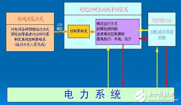
The stability control system is configured based on the stability analysis of the power grid. It is only for the expected operation mode and the predetermined fault type. If there is a way or failure other than the expected one, the stability control system cannot guarantee the stability of the power grid. The second line of defense is the measure taken by people to take the initiative;
The third line of defense is the bottom of the line. Any accidents other than multiple faults and unexpected events cause the system to lose synchronization or frequency and voltage abnormality. The third line of defense device takes control measures to prevent accidents from expanding and prevent system collapse. The line of defense is a means of passively responding to major accidents.
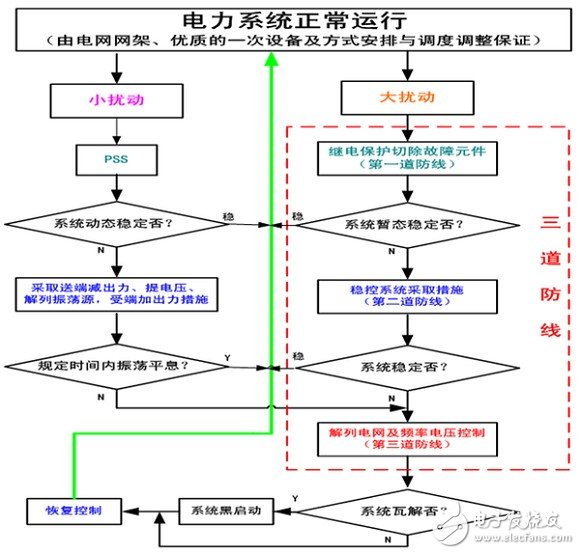
The schematic diagram of the power system stability control phase is as follows:
As mentioned earlier, the stability of the power angle is divided into three types: static stability, transient stability, and dynamic stability.
In the design and operation system, the stability of the following three aspects is mainly calculated. The first category: The maximum amount of analytical calculation is transient stability. Since the operation and failure of the system occur frequently and frequently, the correct evaluation of transient stability is of primary importance for the safe operation of the power system. The second category: less is to calculate and analyze the static stability margin of long-distance heavy-duty lines. In the case of static stability problems, most of them belong to the single system to the main system mode or the single machine accesses the system mode via the large ring network. The third category: the least but most influential interest of researchers is the dynamic and stable computational analysis, which is to determine whether there is a periodic instability problem. Because this kind of stable damage is not common, in actual systems, it is often after the incident that it is carefully analyzed and seeks countermeasures.
Under normal circumstances, the transient stability level of the system is lower than the static stability level of the system. If the stability of the system after large disturbance is satisfied, it can often meet the static stability requirements under normal operating conditions. However, maintaining a certain level of static stability is the basis and prerequisite for achieving transient stability of the system. With a certain static stability margin, it is possible to obtain the transient stability of the system through some simple technical measures under severe fault conditions. Without static stability, the system cannot operate; in some special cases, such as Daihatsu Hydropower and post-accident operation mode, it is also necessary to reduce the system transient stability level and operate in a short period of time. The logical reason for this temporary approach is. The short-circuit fault that affects the system's transient stability is of a probabilistic nature. Therefore, it can be considered that during such short-term operation, serious faults sufficient to cause loss of transient stability will occur at the same time.
Third, the power system is static and stableIt can also be called small interference stability (this argument is different, you can think so).
Static stability refers to the ability of the power system to automatically return to the original operating state after spontaneous disturbance or non-periodic loss of synchronization after a small disturbance in a normal operating state. The static stability problem is actually to determine whether a certain steady state point of the system can be maintained under small disturbances. The stability of the system's small interference depends on the inherent characteristics of the system, regardless of the size of the interference. (If the power system is subjected to small disturbances, in the long process, the stability problem under the action of the automatic regulation and control device is classified as a dynamic stability problem, which is first introduced in this section).
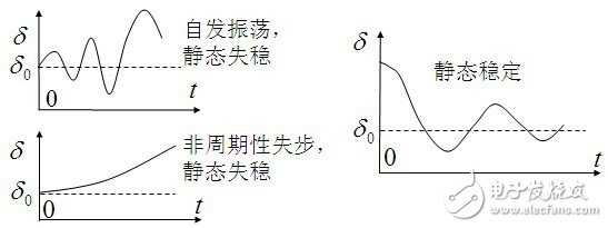
The instability that can occur after a small disturbance in a power system is usually divided into two forms:
Due to the lack of synchronous torque, the generator rotor angle is gradually increased, and the coasting is out of step;
The rotor oscillates due to insufficient effective damping torque. Underdamped oscillation; low frequency power oscillation problem;
The power system contains many electromechanical oscillation modes, and its frequency is usually 0.1~2.0Hz, so it is often called low frequency oscillation.
Inter-area oscillation mode (0.1~1Hz)
Intra-area oscillation mode (1~2Hz)
The small disturbance stability problem is usually an amplifying oscillation caused by insufficient system damping. The small interference analysis method mainly uses the eigen-root method to judge whether the method is stable according to the root of the characteristic equation of the linearized differential equation group of the disturbed motion. .
The essence of the problem lies in: if the frequency of the disturbance of the small unit is close to the inherent electromechanical resonance frequency of the main network system, it will trigger the phenomenon of “resonanceâ€, so that the amplitude of the main network tie line becomes larger and larger, like the relative system generated by the small unit of the low-voltage network. A power oscillation (sway) that is not too big is "amplified" in the main network.
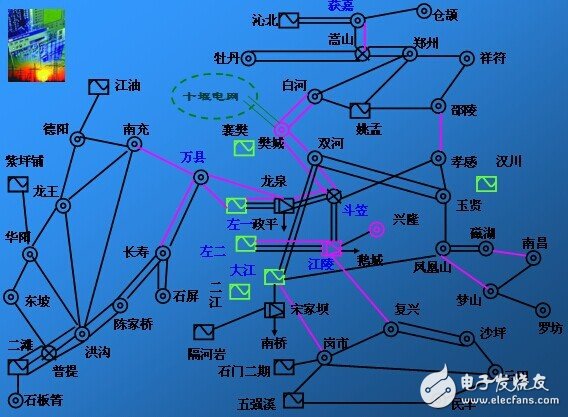
Take the 2005 "10.29" power oscillation of Central China Power Grid as an example:
The oscillation frequency is 0.77 Hz.
The power swing of most 500kV lines in Central China Power Grid, the oscillation amplitude of the Three Gorges external delivery system is large, and the double-line oscillation of the bucket is the largest, with an amplitude of about 730MW.
The oscillation of the power grid in Northwest Hubei was obvious, and many small units (40MW in total) were forced to disengage.
Among the units, the Three Gorges Power Plant has the largest oscillation, and the amplitude of the left second unit (peak-to-peak) reaches 270 MW.
Among the 500kV central point, the left two 500kV bus voltage oscillates the most, with an amplitude of 40kV.
The preliminary conclusion is that the synchronous oscillation caused by weak damping in Hubei Northwest Power Grid leads to the possibility of similar frequency forced oscillation of the main network. However, it is necessary to further analyze the sensitive factors of damping variation in Hubei Northwest Power Grid. It is also necessary to further study the system's forced oscillation. mechanism.
In the research to improve the stability of small disturbances, different oscillation modes should be distinguished, the causes of instability should be identified, and appropriate control measures should be selected in a targeted manner. Especially the control measures of the tie line oscillation mode. It is necessary to establish a system small disturbance stability criterion, such as the damping ratio of all key oscillation modes not less than 3%, the transmission limit of the tie line or the key transmission section. On the basis of a large amount of research on the actual system, a scheduling scheme to avoid small signal instability in the system is determined. Software calculations are generally also checked against these elements.
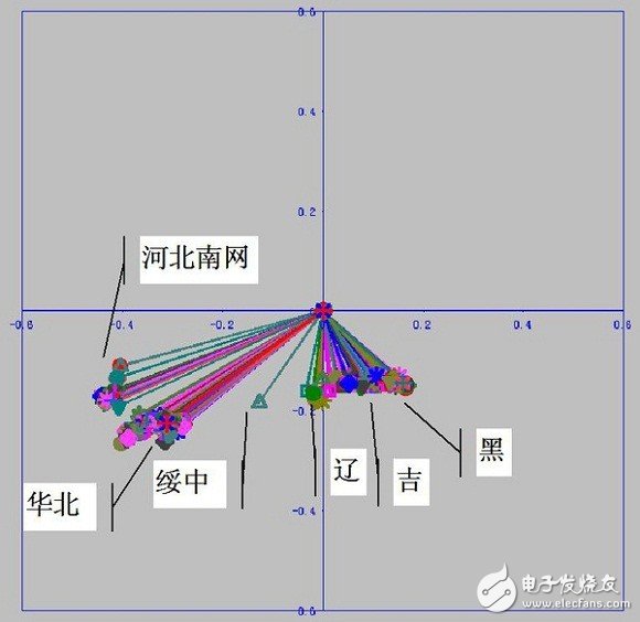
In the calculation process, it mainly analyzes the influence of external network changes (such as section flow and direction) on the dynamic characteristics (characteristic root and damping ratio) of the regional power grid, and then proposes measures such as unit PSS for the weakly damped oscillation mode to avoid grid occurrence. Low frequency oscillation. The following is a small interference analysis modal diagram.
1. Transient stability standard
It is a transient stability problem to consider the effect of large disturbances on the stable operation of the system. To date, national power systems still use the decisive method of generating perturbations to determine the transient stability of the system. The actual system has a large number of disturbance modes. Some of the disturbance modes are extremely complicated due to the simultaneous or successive occurrence of multiple abnormal states, and the disturbance mode generally used for the evaluation of the transient stability of the design and production operation system is extremely simple. E.g. The most commonly used is a single power component with no faults and sudden disconnection due to short-circuit faults, and the corresponding relay protection and automatic device action is considered correct.
Disturbance can be divided into three categories according to the severity of the disturbance and the probability of occurrence:
Class I, single fault (fault with high probability of occurrence): a. Single-phase instantaneous ground fault coincidence success of any line; b. Double-return or multi-loop and ring network of the same-level voltage, single-phase permanent for any return line The fault coincidence is unsuccessful and the faultless three-phase disconnection does not coincide. The three-phase fault of any return line does not overlap; c. Any generator trips or loses magnetism; d. Any transformer of the receiving end system is out of operation; e. Any large load suddenly changes; f. Any one of the AC link faults or faultless disconnects does not coincide; g. DC transmission line single pole fault.
Class II, single serious fault (fault with low probability of occurrence): a. single-phase single-phase permanent fault coincidence unsuccessful and fault-free three-phase disconnection do not coincide; b. any section busbar fault; c. When the two names of the double-circuit line are the same, the single-phase ground fault coincidence is unsuccessful, and the double-circuit line three-phase tripping simultaneously; d. The DC transmission line is bipolar fault.
Class III, multiple serious faults (faults with low probability of occurrence): a. switch refuses when fault occurs; b. relay protection at fault, automatic device malfunction or refusal; d. automatic adjustment device failure; e. multiple Failure; f. loss of large capacity power plants; g. other accidental factors. This piece is now more and more important in China, and the guidelines for the stability regulations are mentioned, but there are not so many specific classifications. The provincial-level dispatch operation mode is not enough for this check, but there should be plans for this in the future.
To check the transient stability, only the system dynamic process calculation needs to be carried out according to the specified fault mode. When it is determined that the system can reach new or return to the original equilibrium state after the disturbance is removed, it can be considered that the requirements are met without having to consider other Additional margins. This is because there is a sufficient margin of safety in the calculation process, as follows (this article does not cover how to calculate, after all, we also use software such as BPA):
As a convention, when performing transient stability calculations, it is required to select the most unfavorable series of operation modes in practice, and metal short-circuit faults occur at the most unfavorable locations, according to the given fault removal time (normally, it is always slightly larger than The actual value) and other combinations of adverse conditions are preconditions. Obviously, it must be stricter than the actual situation, and it has greater security.
As the transient stability check of the design and production operation system, the influence of the torque generated by the DC component in the short-circuit current is always ignored, and the check result under the short-circuit fault mode is further conservative.
At present, the temporary stabilization measures mainly include cutting machine, load shedding, and disconnection of contact lines; electrical braking, quick closing valves, and DC modulation are less applied.
2) A measure to improve the system's transient stability level
Series compensation: series capacitor compensation, which was mentioned before the reactive, but that is not the main, its main role is the transient stability, as to how to improve the transient stability and increase the line transmission limit, textbook There are no mentions on it. In recent years, more controllable series of follow-ups have been used. The other points related to series compensation are as follows:
Series capacitor compensation is only suitable for the case where the system at both the transmitting end and the receiving end is relatively strong. At this time, the line impedance occupies the main component of the entire contact impedance, so the series compensation for it can significantly reduce the integrated impedance to the system, so as to obtain the benefit of increasing the power transmission capacity. However, there are some special problems with series compensation. For example, if the compensation degree of series compensation is large, it will make the traditional correct action of the distance protection as the basic protection difficult, and special measures must be taken; the asymmetric breakdown of the series capacitor gap will affect the zero sequence current protection. Correct and effective action; the series compensation station itself and the protection of the series capacitor are also special problems. The zinc oxide valve plate developed in recent years is used as the overvoltage protection of the series capacitor, which not only can reduce the structure, but also can fully play the series connection. Capacitance enhances the transient stability of the system after fault removal; and if series compensation is used on the high voltage distribution line of the turbine generator set, measures must be taken and measures taken to prevent the possibility of subsynchronous resonance.
The so-called subsynchronous resonance, that is, when the turbo generator is connected to the series-compensated transmission system, if the series resonance rate of the electric system Fe and a certain torsional frequency Fm of the genset shaft system are close to the operating frequency (for example, 50 Hz) If they are complementary (Fe+Fm=60Hz), the electric system will exchange oscillation energy with the mechanical system of the generator shaft shaft system, so that the oscillation will gradually increase until the unit shaft is damaged. For the hydro-generator set, since the rotational inertia of the turbine is much smaller than the moment of inertia of the associated generator, the reaction of the mechanical part is extremely small. Therefore, the problem of subsynchronous resonance does not occur.
Other measures, such as intermediate parallel compensation, adding switch stations, and adding lines, are not common.
3) Secondary automatic measures to improve transient stability level
In the actual project, the second measure is more effective in improving the temporary stability level.
Quick resection
The transient stability problem of the system mainly occurs on the distribution line of the power plant. The rapid removal of faults is the most effective measure to improve the transient stability of the line, and it is also a prerequisite for other safety and automatic measures to function.
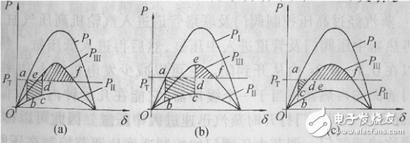
In principle, the power system is to quickly remove the fault, increase the braking energy area, and increase the transient stability of the system.
In the case of a general system, the effect of speeding up the resection fault on increasing the ultimate power supply level. Depending on the grid structure and the location of the plant in the system, it can be considered to be particularly effective for long-haul lines that require high power transmission. The practice of China's power system shows that some systems only accelerate the short-circuit fault removal time near the power plant exit, and obtain the transient stability after maintaining the three-phase short circuit: some systems cancel the fault removal time appropriately and cancel The original required electrical brakes also achieved good transient stability. For the weak receiving end system (the receiving system has less power supply and looser contact), shortening the fault removal time of the transmission line and obtaining larger transient stability benefits. In some cases, you shorten the fault removal time from 0.12S. By 0.1 s, it can replace the effect of cutting 100 MW load.
Therefore, the fault limit cut-off time is also a concern in the power system stability related project.
Under the existing conditions in our country. The fastest fault removal time that can be achieved is that the cut-off time for the near-end fault will be no more than 0.1 s, and the far-end fault cut-off time will be 0.1 s or 0.12 s. According to the needs, it can also achieve near-end faults of no more than 0.08s. The specific fault removal time, the national network project should be analyzed according to the values ​​specified in the national grid security and stability technical specifications.
Automatic reclosing
The important role of automatic reclosing is not only to restore the line that is disconnected due to the fault, but also to maintain the integrity of the system in the case of continuous faults and to avoid the expansion of accidents. The second blackout in New York in 1977 was caused by a continuous failure of multiple loops. During the accident, the 345kV power line was rejected due to the setting of the closing angle being too small (to reduce the impact on the 1000MW unit) and the automatic reclosing and the manual closing were prohibited. Otherwise, it may be possible to avoid a system blackout that caused major social losses this time, shortly afterwards. Just change the closing angle. Some problems with automatic reclosing:
1) Reasonable selection of reclosing time: It can significantly improve the stability of the system when it coincides with the fault unresolved line. The specific analysis is still related to the braking energy area, and the textbook content is not detailed. Whether it is a single-phase or three-phase recloser, when it coincides with a line that has not been eliminated by the fault. The stability level of the system will be significantly reduced, and the single-phase or three-phase reclosing with the best reclosing time will not have a large adverse effect on the stability level of the system even if it coincides with the line that has not disappeared. It is basically similar to the case where electric closing is not performed.
The analysis results show that the coincidence time can be determined according to the optimal condition of the maximum power transmission. Generally speaking, when transmitting heavy load, the initial angle is large, and the swing period after the fault is long: under the same system structure condition, when the light load is transmitted, the initial angle is small, and the swing period after the fault removal becomes short. Therefore, in the case of a lighter transmission load, the reclosing time that satisfies the optimum coincidence time will become shorter. The calculation results show that even if there is more deviation from the optimal coincidence at light load, it generally does not hinder the final stability of the system.
2) Reclosing mode of 220kV line: 220kV network is relatively tight, generally adopts three-phase reclosing mode. This method has many advantages. For example, the reclosing device itself is simple and reliable, and the relay protection is more convenient. When a ground fault occurs, one side first jumps off, and the other side may be quickly cut off by zero-sequence current protection, which plays a part of high-frequency protection. In the actual system, the large ring network or the heavy-duty single-circuit line is suitable for setting the single-phase or three-phase fast reclosing as needed.
In such a special grid structure and operation mode, when the line has a single-phase or multi-phase fault, if it is disconnected without reclosing. The system will lose its stability. If the line is only disconnected for a short time, relying on a successful fast reclosing to enable the grid to quickly restore the original normal wiring, it is possible to maintain the system's transient stability. In this case, it is reasonable to use a coincidence time to meet the required fast reclosing. However, if it coincides with the line that has not been eliminated, and the system loses stability, it is undoubted. At this time, it has to rely on backup measures to stop the oscillation, or cut the machine, load the load, etc. to prevent the loss of stability.
3) Reclosing mode of 500kV line: The power transmitted by the 500kV line accounts for a large proportion of the system capacity. And line faults still account for the majority of single-phase transient faults, and an effective measure to keep these lines safe to operate is to use single-phase reclosing. Unlike the 220kV line, an important issue that must be considered when using a single-phase reclosing on a 500kV line is whether the fault point can quickly self-extinguish the arc (neutral reactance).
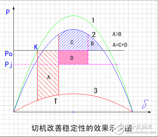
Cutting plan
The most fundamental prerequisite for maintaining the synchronous stability of an electrical power system is to ensure that the transmission capacity of the line is always greater than the maximum power transmitted by the system. Therefore, when the line fails and the transmission capacity is insufficient, the machine must be cut to maintain the system's continued stable operation.
Regardless of the domestic and international systems, hydropower plant cutting machines have been used as an effective means to deal with the above problems, and have already achieved successful experience. However, the cutting machine of thermal power plants has not been widely adopted.
Another key issue to play the role of cutting machine is to hope that the cutting time can be accelerated as soon as possible after the failure occurs, and the slower the cutting. The worse the effect, wait until the other units have stepped into the edge of instability, and then cut the machine to no avail. In order to speed up the cutting time, it is best to act on the transformer side high voltage circuit breaker with fast action, not the generator circuit breaker of the low pressure side slow motion. In addition, in order to quickly reduce the power of the thermal power unit, it is a good idea to close the valve.
Reasonable adjustment of system operation wiring
Strengthening the receiving end system and properly dispersing the external power supply is not only a principle to be followed in building a safe and stable power grid, but also an important stability measure for the operating system when conditions are met and required.
System conditions for sending primary power from a remote source. The stability problem of the operation wiring of this system is often due to the lack of local power supply support, and the system cannot maintain a high level during the power swing of the system after the fault; it is more likely to be affected by the voltage of the terminal bus during the rocking process. The crash and the continuous decline, causing the loss between the receiving end power supply and the external power supply. One of the ways to improve this instability in the operating system is to change the shutdown unit in the receiving system to operate the camera to increase the short-circuit current level of the receiving bus, so that the receiving bus can be maintained during the rocking process. Higher voltage. A more effective measure is to try to separate the remote power sources so that they are not connected in parallel until they are connected to the busbars of the receiving system. In this way, when any power transmission branch fails, the other power supply branches will support the receiving bus voltage as the receiving system power supply, ensuring that the receiving terminal voltage is at a higher level, thereby significantly improving the stability of the system. Sex.
Cut concentrated load
By focusing on the negative pressure, it can increase the operating frequency of the system, can reduce the overload of some power lines, and can improve the voltage level of the receiving end, thus contributing to the safe and stable operation of the system. However, the concentrated load shedding has too much impact on the user, and because of the misoperation caused by remote control, it has more side effects, so it should be used with caution. One of the possible ways to reduce and avoid mis-loading is to increase the local discriminative monitoring of certain parameters (such as voltage reduction) that are cut off, and only when the local discriminating element is actuated and receives a telecut command.
Fast excitation
Fast excitation has always been a common measure to improve transient stability. In a weak transmission system, under the specified fault removal time. Fast excitation is beneficial to improve the line transmission power under transient stability conditions, and the specific effects depend on specific conditions. When using fast excitation, the short-circuit fault of the distribution line can immediately provide the limit excitation voltage to the generator rotor circuit. After the fault is removed, the terminal voltage of the generator can be quickly recovered or even exceeded the rated value for a short time. The large braking area increases the transient stability of the system and the limit power that the line allows to transmit increases.
But only when transmitting a large amount of power on a very weak contact line. Fast excitation can show certain effects. Compared with the rapid resection fault, the fundamental reason for the fast excitation to the transient stability is that it can increase the braking area, it is difficult and reduce the fault removal time. The double effect is comparable.
In the actual power grid, the power system transient stability control process is as follows:
Dynamic instability (non-attenuating electromagnetic oscillations) has occurred many times in other power systems in countries around the world. The basic three cases are the system of the generator set connected by the long-distance line, the weakly connected system and the long-chain structure.
The root cause of dynamic instability is that the damping torque of the system is negative. The oscillation of the system caused by large or small disturbances causes the oscillation to gradually diverge. Either cause a de-column between systems, or the amplitude of the oscillation eventually tends to a certain value due to the nonlinearity of certain parameters in the system.
The causes of dynamic instability at home and abroad are mostly due to the negative damping effect of the voltage regulation system.
In domestic and foreign systems, when dynamic instability occurs, it is often not prepared in advance, and emergency measures must be taken. The temporary effective measures actually taken have the following three points. 1) Reduce the active output of the generator to reduce the transmission power of the distribution line or the tie line between the systems (but there are cases where the dynamic instability of the tie line transmission power suddenly occurs) 2) Increase the generator terminal voltage. 3) Exit the voltage regulator, or reduce the magnification and so on.
The most effective way to suppress the dynamic instability is to introduce an additional link in the input loop of the voltage regulator that can reflect the change of the generator speed, and the change of the generator terminal voltage can be in phase with the change of the rotational speed to achieve the excitation system. The final requirement for positive damping torque. This additional amount of voltage regulator is actually introduced, and this additional voltage regulator is introduced into the reaction speed, called the Power System Stabilizer (PSS) in the United States and Additional Feedback (AF) in Europe.
Dynamic stability is actually a good research direction. It includes: selecting the location of the generator generator to install the PSS; selecting the reactive bus voltage frequency or rotor speed, or output power as the signal intrusion of the PSS device, and determining the dominant oscillation frequency and reasonable choice of PSS loop parameters, etc. There is a lot of learning to do. However, the actual dynamic instability accidents are often difficult to predict.
Sixth, the power system frequency stability
The frequency reflects the basic state of the supply and demand balance of active power in the power system.
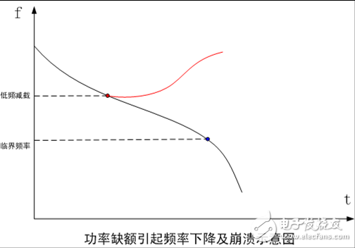
If the operating frequency of the power system deviates too much from the rated value, it will have an adverse impact on the power users. When the power plant is the most affected, when the power supply frequency drops, the power output of the generator is reduced, which is even more dramatic. The imbalance between supply and demand further contributed to the decline in frequency and even caused the power plant to stop.
Mainly written is the content of low frequency load shedding.
1) Low frequency load shedding criteria
In the power system, the automatic load shedding device according to the frequency reduction must be configured so that the load capacity of the reserved operation can be adapted to the power generation capacity at any time to ensure that the system frequency can be quickly recovered after the sudden occurrence of the active power shortage. Close to the declination value. The design and setting guidelines for reducing the automatic load shedding by frequency are mainly considered as follows:
If there is no special requirement, it is generally recommended that the time to fall below a certain low frequency value (for example, 47 Hz) is not greater than a specified time (for example, 0.5 s) in any case.
In the frequency reduction process under any possible circumstances, the low frequency value and the elapsed time of the system should be ensured to match the low frequency protection of the large unit to ensure that these large units continue to operate in a network to avoid further deterioration of the accident.
If the system frequency is over-modulated due to over-cutting, the maximum value must not exceed a certain value, such as 51HZ, to avoid over-frequency protection tripping of large units in the system. This has actually occurred a lot of load-cutting over-frequency accidents. (At this time, you have to cut the machine automatically.)
2) Small system loses big power
Small systems lose large power and there are two small systems that lose large power. One is that the terminal system supplies a considerable proportion of the power supply from the main system, the other is the newly established power grid, and the small system is equipped with a large capacity unit. When the main system power supply or large unit is lost, the system's active power shortage may be as large as 50% or even hundreds of percent. This is a particularly serious situation. China's operating experience has confirmed that when the active power shortage is too large, voltage collapse may occur at the same time as the frequency collapses, even if the voltage collapses faster than the frequency collapse, the voltage is reduced overall, the overall overcurrent of the operating unit is reduced, and the system frequency is decreased. Does not highlight serious phenomena. Obviously, under such special grid conditions, the method of dealing with such a large power shortage is dealt with. Can no longer be a general low frequency load shedding. Practical experience shows that the correct way to deal with such accidents is to pre-arrange the grid operation wiring that is ready at any time (for example, arrange the power supply and load to match the busbar), when the main unit of the main power supply is lost, Interlocking removes the concentrated load that is appropriate.
The frequency stability is really not much involved, so the content is not rich enough.
Seven, power system voltage stability
The voltage stability is more complicated, and many things are not conclusive, so I only know a little about this one.
Many have mentioned in the previous reactive power compensation and voltage adjustment, mainly to write the rest.
The voltage stability is defined in the guide as: After the power system is disturbed or disturbed by a small disturbance, the system can maintain or return to the allowable range without the ability to collapse. In this way, voltage stability is also divided into static, transient and dynamic aspects. The specific meaning is similar to the aforementioned power angle.
Globally, most of the blackouts have reached a certain stage, causing voltage collapse problems, and then leading to serious consequences. The core problem is still lack of power, specifically the following:
Under heavy load operation, the system load continues to increase, the system runs standby (especially reactive), and the transmission line current is close to the maximum power limit.
A large sudden disturbance, such as the loss of the generator set, the successive tripping of the transmission line, and so on. ? On-load tap changer ULTC negative voltage regulation.
Generator over-excitation limiter OEL.
The lack of coordination such as relay protection and low-frequency load shedding is an important cause of voltage instability.
Weakly connected AC and DC systems.
Voltage collapse is often shown as slow voltage decay due to the accumulation of many voltage control devices and protection systems and their interactions. In many cases, voltage instability and rotor angular instability are coupled to each other.
Many theories in scientific research are used in voltage stability research, such as bifurcation theory, but in actual engineering, there are still some common methods.
The first is the static analysis method, which mainly calculates some indicators and combines the QV curve to analyze the safety and stability margin of the voltage. For example, sensitivity method, dQ/dV node criterion, etc., can generally be calculated according to software power flow, and combined with certain indicators to analyze voltage static security and stability.
As for dynamic analysis, voltage stability is essentially a dynamic problem, compared to the typical time domain simulation method. The transient stability of the voltage and the stability of the power angle are in a time frame; as for the dynamic stability, it lasts for a long time, and some accidents occurring internationally belong to this category.
As an example: a large generator set trips, followed by a 500KV important line trip.
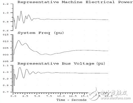
Transient analysis shows that within 20s after the accident, the frequency and voltage are stabilized after swaying; the voltage is reduced. The system showed a more optimistic response.
Dynamic analysis shows that it is a long-term time frame, considering load, generator, ULTC, excitation protection, AGC, gas machine, etc. A bad situation under simulation:
Speed ​​governor action, increase power generation (with differential adjustment) --- AGC function, power re-scheduling of the whole network --- increase the pressure on the grid (cause: according to the principle of economic dispatch, not the most suitable location. Some lines may be under pressure);
The voltage drop causes the load power to drop (considering the static characteristics of the load voltage) --- excess power --- frequency rise --- AGC action, reducing power generation.
After 80s, some OEL actions of the generator reaching the reactive limit cause Qlimit to Qnominal -- further voltage levels drop. Other generators increase the reactive output.
After 120s, the dynamic combination of load dynamics and ULTC leads to a system voltage drop -- further aggravated by AGC (AGC reduces power generation to reduce frequency, while generators that reduce power generation are located at the load center - equivalent to overload , need reactive support to increase --- voltage drop ;)
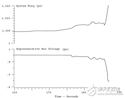
160såŽï¼Œå¦å¤–一些å‘电机由于OEL作用而使Qlimit致Qnominal,å‡å°‘æ— åŠŸè¾“å‡ºï¼ŒåŠ å¤§äº†å’ŒåŠ é€Ÿäº†ç”µåŽ‹ä¸‹é™â€•â€•â€•å‘电机失æ¥ï¼Œä½ŽåŽ‹ä¿æŠ¤è€Œå¤±åŽ»ä¸€äº›å‘电机。
电压崩溃,频率失稳。
功角ä¸ç¨³å®šå’Œç”µåŽ‹ä¸ç¨³å®šç»å¸¸åŒæ—¶å‘生,一ç§å½¢å¼çš„ä¸ç¨³å®šå¯å¯¼è‡´å¦ä¸€ç§å½¢å¼çš„ä¸ç¨³å®šã€‚æ高电压稳定性的控制措施主è¦æœ‰å‘ç”µæœºæ— åŠŸæŽ§åˆ¶ï¼ˆåŠ±ç£æŽ§åˆ¶ï¼‰ã€ä½Žç”µåŽ‹åˆ‡è´Ÿè·ã€é™æ¢è¡¥å¿è®¾å¤‡ï¼ˆSVCã€STATCOM)ç‰ï¼Œä½Žç”µåŽ‹åˆ‡è´Ÿè·æŽªæ–½æ˜¯ç”µåŽ‹ç´§æ€¥æŽ§åˆ¶æœ€åŸºæœ¬è€Œæœ‰æ•ˆçš„措施。对于å¤æ‚电网,仅é 分散安装的低压切负è·è£…置往往ä¸èƒ½æœ‰æ•ˆè§£å†³ç”µåŽ‹ç¨³å®šé—®é¢˜ï¼Œéœ€è¦é…ç½®å¤šä¸ªåŽ‚ç«™çš„ç”µåŽ‹ç¨³å®šæŽ§åˆ¶ç³»ç»Ÿï¼Œæ ¹æ®å¤šä¸ªç›¸å…³ç«™ç‚¹çš„电压水平åŠç³»ç»Ÿçš„è¿è¡ŒçŠ¶æ€ï¼ˆåŒ…括故障)æ¥è¿›è¡Œå†³ç–。
å…«ã€å¤±ç¨³å¯¹ç–所有国内外é‡å¤§ç³»ç»Ÿäº‹æ•…çš„äº§ç”Ÿï¼Œå‡ ä¹Žéƒ½æ˜¯ç”±ç³»ç»Ÿå¤±åŽ»ç¨³å®šè€Œæ‰©å¤§ï¼Œå› æ— é¢„å®šå¯¹ç–,而åŽå‘展为ç¾å®³æ€§åŽæžœçš„。长期的è¿è¡Œå®žè·µè¯å®žã€‚ä¸ç®¡å¯¹ç³»ç»Ÿç¨³å®šæ€§çš„è¦æ±‚å¦‚ä½•ä¸¥æ ¼ã€æŽªæ–½å¦‚何完善,总å¯èƒ½å› 一些事先ä¸å¯é¢„计的å„ç§å¶ç„¶å› ç´ å åŠ ï¼Œäº§ç”Ÿç¨³å®šç ´å事故。而过份æ高对系统稳定性的è¦æ±‚。需è¦å¤§é‡çš„æŠ•èµ„ã€‚ä¸€ä¸ªè¾ƒå¼±è€Œæœ‰æŽªæ–½å‡†å¤‡çš„ç³»ç»Ÿï¼Œä¼šæ¯”è¾ƒå¼ºè€Œæ— æŽªæ–½å‡†å¤‡çš„ç³»ç»Ÿæœ‰æ›´å¥½çš„è¿è¡Œæ•ˆæžœã€‚
当主系统å‘生éšå®šç ´ååŽï¼Œå…³é”®é—®é¢˜åœ¨äºŽå¦‚何能åˆç†è€Œå¿«é€Ÿåœ°å¹³æ¯æŒ¯è¡ï¼Œå’Œæœ€å¿«åœ°ä½¿ç³»ç»Ÿæ¢å¤æ£å¸¸ã€‚将振è¡ç€çš„两侧系统解列,å¯ä»¥å¹³æ¯æŒ¯è¡ï¼Œä½†è¦åœ¨å¤±åŽ»åŒæ¥çš„系统ä¸å®žçŽ°åˆç†çš„解列,必须满足两个基本æ¡ä»¶ï¼š1)解列åŽçš„两侧系统必须å„自能ä¿æŒåŒæ¥è¿è¡Œï¼›2)解列åŽä¸¤ä¾§ç³»ç»Ÿçš„æœ‰åŠŸæ— åŠŸä¾›éœ€èƒ½å¤ŸåŸºæœ¬å¹³è¡¡ã€‚å¾ˆæ˜Žæ˜¾ï¼Œä¸åŒæ—¶æ»¡è¶³è¿™ä¸¤ä¸ªæ¡ä»¶çš„解列,åªèƒ½ç»™ç³»ç»Ÿå¸¦æ¥æ›´å¤§çš„混乱,必然以长时间大é¢ç§¯åœç”µè€Œå‘Šç»ˆï¼Œè¿™æ˜¯å›½å¤–和国内都ä¸æ¢ä¸€æ¬¡å‡ºçŽ°è¿‡çš„情况。
故障下选择性解列,或者ä¿æŒç³»ç»Ÿçš„完整性,一直是业内讨论的问题,没有定论。
我国系统长期的è¿è¡Œå®žè·µè¯´æ˜Žï¼Œå¯¹ä»˜ç³»ç»ŸæŒ¯è¡çš„有效办法,是在系统振è¡æ—¶å°½å¯èƒ½ä¿æŒæ•´ä¸ªä¸»ç³»ç»Ÿçš„完整性,ä¸å› 振è¡è€Œä½¿çº¿è·¯åŠæœºç»„乱解列,åŒæ—¶å¯¹é€ç«¯ç”µåŽ‚å³æ—¶åŽ‹å‡ºåŠ›ï¼Œå°±å¯ä»¥å¿«é€Ÿå¹³æ¯æŒ¯è¡ï¼Œå› ä½äºŽæŒ¯è¡ä¸å¿ƒé™„近而甩掉的部分负è·ä¹Ÿå¯ä»¥å› æ¤è€Œå¿«é€Ÿæ¢å¤ä¾›ç”µï¼Œä»Žè€Œæ¢å¤ç³»ç»Ÿçš„æ£å¸¸è¿è¡Œã€‚
å¹³æ¯ç³»ç»ŸæŒ¯è¡çš„有效措施,是压é€ç«¯æœºç»„å‡ºåŠ›ï¼Œå¢žåŠ å—端机组出力,使系统ä¸æœºç»„é€æ¸æŒ‰åŒä¸€å¹³å‡é¢‘率è¿è¡Œã€‚在一个å¤æ‚系统ä¸ï¼Œåœ¨ä¸åŒçš„事故情况下,一个电厂所处的é€å—端ä½ç½®å¯èƒ½å˜åŒ–。压错了实际ä½ä¸Žå—端的水电机组出力而使振è¡åŠ 剧的情况,在我国,ä¸åªåœ¨ä¸€ä¸ªç³»ç»Ÿä¸å‘ç”Ÿè¿‡ï¼Œå› è€Œå»¶é•¿äº†å¹³æ¯æŒ¯è¡çš„æ—¶é—´ã€‚å› æ¤ï¼Œéœ€è¦ç”¨è‡ªåŠ¨è£…ç½®æ¥åˆ¤åˆ«ã€‚
系统æŒç»æŒ¯è¡ã€‚在接近振è¡ä¸å¿ƒçš„部分负è·ä¼šå› 电压的周期性严é‡é™ä½Žè€Œè‡ªåŠ¨æˆ–手动地被切除。但是,åªè¦ç³»ç»Ÿç»“构完整,机组ä¿ç•™è¿è¡Œï¼Œä¸€å½“振è¡å¹³æ¯æ—¶ï¼Œè¿™äº›è¢«åˆ‡æŽ‰çš„è´Ÿè·å°±å¯ä»¥è¿…速地æ¢å¤ä¾›ç”µï¼Œè¿™æ¯”之于系统全åœåŽçš„è´Ÿè·æ¢å¤ï¼Œç»“果当然更好。
å¦ä¸€ä¸ªé—®é¢˜ï¼Œç³»ç»ŸæŒç»æŒ¯è¡å¯¹å¤§åž‹å‘电机组有何严é‡å½±å“。è¦æ±‚振è¡æ—¶æœºç»„ä¸è§£åˆ—,作çŸæ—¶é—´å¤±æ¥è¿è¡Œï¼Œç‰¹åˆ«å¯¹å¤§åž‹æ±½è½®å‘电机组说æ¥ï¼Œèƒ½å¦é€ æˆä¸¥é‡çš„åŽæžœï¼Ÿ
CIGRE的结论为:从兼顾系统安全与机组安全,建议:å¯ä»¥å…许汽轮å‘电机在一定æ¡ä»¶ä¸‹ä½œçŸæ—¶é—´çš„失æ¥è¿è¡Œã€‚这个æ¡ä»¶å¯ä»¥ç®€è¦åœ°æŒ‰åœ¨å¤±æ¥è¿‡ç¨‹ä¸æŒ¯è¡ä¸å¿ƒæ˜¯å¦å¤šæ¬¡è½å…¥å‘电机å‡åŽ‹å˜åŽ‹å™¨ä¹ƒè‡³å‘ç”µæœºæœ¬èº«ä¸ºæ ‡å‡†ï¼Œå…许的振è¡æ¬¡æ•°å¯è€ƒè™‘订为20次跳闸。
最åŽä¸€ç‚¹å°±æ˜¯å…³äºŽç³»ç»Ÿè§£åˆ—点的,是å¦éœ€è¦ä¸Žå¦‚何形æˆå‡†å…¨å›½æ€§è´¨çš„统一电网,安排解列点是其ä¸éœ€è¦è®¤çœŸç ”究的一个é‡è¦é—®é¢˜ã€‚失æ¥è§£åˆ—是电网第三é“防线的é‡è¦ç»„æˆéƒ¨åˆ†ã€‚
å…³äºŽè§£åˆ—ç‚¹çš„é€‰æ‹©ï¼šç›®æ ‡æ˜¯åœ¨é¢„å®šçš„è§£åˆ—ç‚¹å°†ç”µç½‘è§£åˆ—åŽç³»ç»Ÿå¤±æ¥æŒ¯è¡çŽ°è±¡è¢«æ¶ˆé™¤ï¼Œç”µç½‘的解列点应尽é‡é€‰åœ¨ç½‘é—´è”络线。系统解列åŽå½¢æˆé€ç«¯ä¸Žå—端两部分电网,å„部分电网内的功率一般ä¸å¯èƒ½å¹³è¡¡ï¼Œé€ç«¯ç”µç½‘通过切机ã€å‡å‡ºåŠ›ï¼Œå—端电网通过切负è·æŽªæ–½å¯ä¿æŒå„部分电网的频率或电压的稳定性。在解列点选择时应尽é‡æŠŠå¸¦è´Ÿè·çš„å˜ç”µç«™æˆ–本站的负è·ç•™åœ¨é€ç«¯ç”µç½‘一侧。
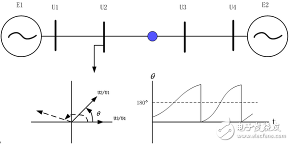
最佳的解列时刻:系统å‘生失åŽåº”尽快将电网解列,但判æ–系统失æ¥çš„判æ®æ˜¯ç³»ç»Ÿé€å—端两个ç‰å€¼æœºçš„功角摆过180åº¦ï¼Œå› æ¤æœ€å¿«çš„解列时刻是功角过180度那一时刻(è”络线两侧æ¯çº¿ç”µåŽ‹ç›¸ä½å·®ä¹Ÿæ˜¯180度)。
至于失æ¥è§£åˆ—判æ®ï¼Œç›¸å¯¹æ¯”较ç†è®ºï¼Œè€Œä¸”å¾ˆå¤šæ–¹æ³•æ— æ³•ç»Ÿä¸€ï¼Œä¸€èˆ¬é‡‡ç”¨æŒ¯è¡ä¸å¿ƒä¸¤ä¾§æ¯çº¿ç”µåŽ‹ç›¸é‡ç›´æŽ¥æ¯”相原ç†ï¼Œå½“两侧æ¯çº¿ç”µåŽ‹ç›¸ä½å·®è½¨è¿¹è¶…过180度时认为系统失去åŒæ¥ï¼Œä¸”振è¡ä¸å¿ƒåœ¨ä¸¤ä¸ªæ¯çº¿ä¹‹é—´ã€‚
除了上述综åˆè§£åˆ—之外,低压解列也是三é“防线的组æˆéƒ¨åˆ†ï¼Œæš‚稳问题å‘生åŽï¼Œå¦‚没有稳定控制措施或稳控拒动,系统的暂稳问题就会转å˜ä¸ºç”µåŽ‹ç¨³å®šé—®é¢˜ã€‚æ¤æ—¶ç”±äºŽç”µåŽ‹ä¸‹é™é€Ÿåº¦å¤ªå¿«ï¼Œå¸¸è§„的低压切负è·è£…ç½®åŠä½ŽåŽ‹è§£åˆ—装置å¯èƒ½å› dU/dt过大而被é—é”;而系统的功角åˆæ²¡æœ‰æ‘†å¼€ï¼Œå³ä¸ä¼šå‡ºçŽ°å¤±æ¥æŒ¯è¡çš„特å¾ï¼Œå¸¸è§„的失æ¥è§£åˆ—装置也动作ä¸äº†ï¼Œç³»ç»Ÿé¢ä¸´ç”µåŽ‹å´©æºƒã€‚设置专用的低压解列装置å¯è§£å†³ä¸Šè¿°é—®é¢˜ï¼›ç³»ç»Ÿè§£åˆ—åŽç”µåŽ‹ç¨³å®šé—®é¢˜æ¶ˆå¤±è½¬ä¸ºé€å—端电网的频率稳定问题,处ç†èµ·æ¥ç›¸å¯¹ç®€å•çš„多。
ä¹ã€å…¨åœåŽç³»ç»Ÿæ¢å¤ä½œä¸ºç”µåŠ›ç³»ç»Ÿå®‰å…¨æŽªæ–½çš„最åŽä¸€æ¡ï¼Œæ˜¯å‡†å¤‡å¦‚æžœå‘生系统全部åœç”µæˆ–者å‘生大é¢ç§¯åœç”µçš„é‡å¤§äº‹æ•…åŽï¼Œå¦‚何能够快速æ¢å¤ç³»ç»Ÿå’Œå¯¹å¹¿å¤§ç”¨æˆ·çš„供电。在现代电力系统ä¸ï¼Œéƒ½åˆ¶è®¢äº†é€‚åˆæœ¬ç³»ç»Ÿæƒ…况的全åœåŽçš„系统æ¢å¤æ–¹æ¡ˆã€‚
ä¸åŒçš„电力系统有ä¸åŒçš„具体特点,但在æ¢å¤ç³»ç»Ÿçš„过程ä¸ï¼Œéƒ½æœ‰ä¸€äº›å…±æ€§é—®é¢˜ã€‚
1)起动电æºã€‚在分区进行æ¢å¤çš„æŸä¸ªåŒºåŸŸå†…,都必须有起动电æºã€‚水电机组用作起动电æºæœ€ä¸ºæ–¹ä¾¿ã€‚å¯èƒ½çš„问题是如果机组容é‡è¾ƒå°ï¼Œåˆç»é•¿è·ç¦»é«˜åŽ‹çº¿è·¯æŽ¥å…¥ç³»ç»Ÿæ—¶ï¼Œå¯èƒ½äº§ç”Ÿè‡ªåŠ±å‚²æˆ–末端电压过高,但如果能事先接入æŸäº›è´Ÿè,一般的过电压问题题都å¯èƒ½å¾—到缓解。ç«ç”µæœºç»„也应当能作为起动电æºï¼Œé—®é¢˜æ˜¯è¦å…·æœ‰çƒæ€å†èµ·åŠ¨çš„能力。而关å¥åœ¨äºŽæŠŠæ¡å¥½æŸäº›å…许的时间间隔。
2ï¼‰æ— åŠŸåŠŸçŽ‡å¹³è¡¡ã€‚åœ¨è¶…é«˜åŽ‹ç”µç½‘çš„æ¢å¤è¿‡ç¨‹ä¸ï¼Œæ— 功功率平衡是一个严é‡é—®é¢˜ã€‚一般说æ¥ï¼Œæœ‰ä¸¤ç§å¯èƒ½çš„æ¢å¤ç”µç½‘çš„åšæ³•ï¼šä¸€ç§åšæ³•æ˜¯é¿å¼€çº¿è·¯å……电和电压问题,按系统å‘展过程的相åŒé¡ºåºæ¢å¤ç³»ç»Ÿï¼Œå°†è¶…高压电网置于最åŽæ¢å¤ã€‚但这ç§åšæ³•çš„明显缺点是相当程度地延长了整个的æ¢å¤æ—¶é—´ã€‚å¦ä¸€ç§åšæ³•æ˜¯å…ˆæ¢å¤è¶…高压电网,优点是å¯ä»¥åŠ 速系统的æ¢å¤ï¼Œä½†å¿…须对æ“作顺åºè¿›è¡Œç»†è‡´å®‰æŽ’。例如在超高压线路充电å‰ï¼šâ‘ 先安排接入一定容é‡ï¼ˆæœ€å¥½æ˜¯ä½ŽåŠŸçŽ‡å› 数)的负è·;②将并è”电抗器先接入线路;â‘¢æ–å¼€é™ç”µç”µå®¹å™¨;④将å‘电机端电压置于厂用电å…许的最低电压值åŒæ—¶å°†è‡ªåŠ¨ç”µåŽ‹è°ƒèŠ‚器投入è¿è¡Œå¹¶å°†å˜åŽ‹å™¨ç”µåŽ‹æŠ½å¤´å…ˆè°ƒåˆ°åˆé€‚ä½ç½®ç‰ç‰ã€‚实施这些æ¥åºï¼Œèƒ½å¦ä¿è¯å®‰å…¨ï¼Œä¸å‘生过电压问题,当然需è¦äº‹å…ˆçš„ä»”ç»†ç ”ç©¶åˆ†æžã€‚
3)有功功率平衡。为了使起动电æºèƒ½åœ¨æœ€ä½Žè´Ÿè·æ°´å¹³ä¸‹ç¨³å®šè¿è¡Œå’Œä¿æŒç½‘络电压有åˆé€‚的水平,一开始往往需è¦åŠæ—¶é€‚当地接通一定容é‡çš„è´Ÿè·ï¼Œä½†åˆåªèƒ½å°‘é‡å¢žåŠ è´Ÿè·ï¼Œä»¥ä¿æŒè¿è¡Œé¢‘率在åˆç†çš„å…è®¸èŒƒå›´å†…ã€‚å› æ¤ï¼Œä¸€èˆ¬å¾€å¾€é¦–先适于æ¢å¤è¾ƒå°çš„ç›´é…è´Ÿè·ï¼Œè€ŒåŽé€æ¥åœ°å¸¦è¾ƒå¤§çš„ç›´é…è´Ÿè·ä¸Žç”µç½‘è´Ÿè·ã€‚å—按频率é™ä½Žè‡ªåŠŸå‡è´Ÿè·æŽ§åˆ¶çš„è´Ÿè·ï¼Œç†åº”åªåœ¨æœ€åŽé˜¶æ®µæ¢å¤ã€‚å›½å¤–å‡ ä¸ªç”µåŠ›ç³»ç»Ÿçš„ç»éªŒæ•°æ®ä¸ºè´Ÿè·é‡ä¸å¤§äºŽå‘电é‡çš„5%å³å¯æ»¡è¶³è¦æ±‚。
åã€ç³»ç»Ÿç¨³å®šå¯¹ç»§ç”µä¿æŠ¤çš„è¦æ±‚这里讲的继电ä¿æŠ¤åº”包括ä¿æŠ¤è£…置与相关的通é“ã€äºŒæ¬¡å›žè·¯ã€‚
1)在被ä¿æŠ¤çš„元件没有故障或故障å‘生在区外时应ä¸è¯¯åŠ¨ä½œã€‚
由于通é“接å—与å‘é€æ—¶å»¶çš„ä¸ä¸€è‡´å¼•èµ·çš„光纤纵差ä¿æŠ¤è¯¯åŠ¨ã€ç”±äºŽäº¤æµä¸²å…¥ç›´æµç”µæºå›žè·¯å¼•èµ·ä¿æŠ¤åŠè¿œè·³è£…置误动ã€ç”±äºŽçº¿è·¯è¿‡è½½å¼•èµ·çš„è·ç¦»ä¸‰æ®µè¯¯åŠ¨ä½œç‰äº‹æ•…å›½å†…è¿‘å‡ å¹´ä»å¤šæ¬¡å‘生,有的诱å‘了大范围åœç”µäº‹æ•…。
2)在被ä¿æŠ¤çš„元件区内å‘生故障时应ä¸æ‹’动。
由于直æµç”µæºæ¶ˆå¤±å¼•èµ·ä¿æŠ¤æ‹’动导致大范围åœç”µäº‹æ•…国内多次å‘生,如:05年“9.26â€æµ·å—大åœç”µäº‹æ•…ï¼›07年“10.27â€ä¸Šåˆ10:10上海å¾æ±‡åŒº220åƒä¼é•¿æ˜¥å˜ç”µç«™åœç”µäº‹æ•…ï¼ˆé€ æˆä¸Šæµ·å¾å®¶æ±‡ã€ç”°æž—ã€é¾™åŽç‰åœ°åŒºåœç”µï¼Œå±…æ°‘ã€å•†æˆ·ç”¨ç”µå—到影å“,地é“1ã€2ã€4å·çº¿éƒ¨åˆ†åŒºæ®µå¤±ç”µï¼‰ç‰ã€‚ä¿æŠ¤è£…置实现了åŒé‡åŒ–,但å‘ä¿æŠ¤ä¾›ç”µçš„ç›´æµç”µæºç‰å›žè·¯å¦‚æžœä¸åŒé‡åŒ–ä¿æŠ¤çš„å¯é 性åˆå¦‚何ä¿è¯ã€‚
3)在系统å‘生异æ¥æŒ¯è¡æœŸé—´ä¿æŠ¤è£…置应å¯é é—é”。
国内ä¿æŠ¤è¿™ä¸€é—®é¢˜è§£å†³å¾—较好,但国外ä¿æŠ¤è¿™æ–¹é¢é—®é¢˜è¾ƒå¤§ï¼Œ03年的“8.14â€ç‰å¤§äº‹æ•…ä¸åœ¨ç³»ç»ŸæŒ¯è¡è¿‡ç¨‹ä¸æ—¶ä¿æŠ¤æ— 选择的动作,使系统事故扩大。
4)110kV电压ç‰çº§ä»¥ä¸Šçš„线路ä¸åº”é…置过负è·è·³é—¸ä¿æŠ¤ï¼Œè·ç¦»ä¸‰æ®µå®šç½®åº”躲过该线路å¯èƒ½å‡ºçŽ°çš„严é‡è¿‡è´Ÿè·æƒ…况。
5)对于最高电压ç‰çº§ä¸º110kVçš„çœçº§ç”µç½‘(西è—ç‰ï¼‰ï¼Œé‡è¦è¾“电线路的主ä¿æŠ¤åº”考虑åŒé‡åŒ–é…置,并应设置æ–路器失çµä¿æŠ¤ã€‚
6)低压ä¿æŠ¤è£…ç½®ä¸ä¸å®œå…¼ç®¡ä½Žé¢‘ã€ä½ŽåŽ‹å‡è½½åŠŸèƒ½ã€‚继电ä¿æŠ¤ä¸Žå®‰å…¨è‡ªåŠ¨è£…置应å„å¸å…¶èŒï¼Œåˆ†å·¥æ˜Žç¡®ï¼Œç®¡å¥½è‡ªå·±åˆ†å†…的事就很好了。
7)远åŽå¤‡ä¿æŠ¤çš„é•¿å»¶æ—¶å’Œæ— é€‰æ‹©æ€§é—®é¢˜ã€‚æŸäº›ç”µç½‘æ出利用区域电网的信æ¯æž„建“网路ä¿æŠ¤â€ã€â€œå¹¿åŸŸä¿æŠ¤â€ï¼Œè¯•å›¾è§£å†³è¿œåŽå¤‡çš„é…åˆé—®é¢˜å’Œæ— 选择性问题,目å‰ä¸€èˆ¬ä»…å±€é™äºŽ110kV以下的电网,采å–的方法类似于安全稳定控制系统的æ€è·¯ã€‚
最åŽæ€»ä½“æ¥è¯´ï¼Œç›®å‰ç”µç½‘现况ä¸çš„稳定问题还是很多的:主è¦æ˜¯ï¼š
安全稳定控制系统在æ高电网输é€èƒ½åŠ›ã€é˜²æ¢å¤§äº‹æ•…æ–¹é¢å‘挥ç€é‡è¦çš„作用,但稳控装置/ç³»ç»Ÿæ ‡å‡†åŒ–ä¸å¤Ÿï¼Œä¸€äº›ç”µç½‘稳控系统软件过于å¤æ‚,测试手段ä¸å®Œå–„,装置误动导致的切机切负è·äº‹æ•…近期时有å‘生。
电网互è”åŽç³»ç»Ÿçš„动æ€ç¨³å®šé—®é¢˜çªå‡ºäº†ï¼Œä½†ç›®å‰çš„仿真手段还ä¸èƒ½æ£ç¡®åˆ†æžå’Œå†çŽ°æ‰€å‘ç”Ÿçš„äº‹æ•…ï¼Œå› è€Œè¯±å‘低频振è¡çš„真æ£åŽŸå› 往往还ä¸æ¸…楚,低频振è¡å‡ 乎æ¯å¹´éƒ½æœ‰å‘生,至今我们还没有有效的手段æ¥é¢„测和彻底é¿å…。
电压稳定问题已æˆä¸ºç”µç½‘安全的一大潜在问题,失去大电æºã€äº‹æ•…过程ä¸æ½®æµå¤§è½¬ç§»ã€ä¸»ä¿æŠ¤æ‹’动åŠå¼€å…³å¤±çµã€ç¨³æŽ§ç³»ç»Ÿæ‹’动ç‰ï¼Œéƒ½æœ‰å¯èƒ½ä¼šå¯¼è‡´ç”µåŽ‹å´©æºƒäº‹æ•…。
稳定这å—先就这么多,以åŽä¼šæœ‰å®Œå–„。其实实际工程ä¸ä¸»è¦æ˜¯ä»¿çœŸè®¡ç®—,梳ç†ä¸€é体系也清楚了ä¸å°‘,实际工程ä¸ç¨³å®šè®¡ç®—必须结åˆç”µç½‘网架分æžï¼Œè¿è¡Œæ–¹å¼åˆ†æžä»¥åŠä¸€äº›è§„程规范,å†å‘现问题æ出解决措施,至于结åˆä¿æŠ¤çš„一些东西就更å¤æ‚äº†ï¼Œè¿™æ ·æ˜¯ä¸€äº›å¤æ‚的安稳专题的难度所在。
ZGAR GenkiIppai Pods 5.0
ZGAR electronic cigarette uses high-tech R&D, food grade disposable pod device and high-quality raw material. All package designs are Original IP. Our designer team is from Hong Kong. We have very high requirements for product quality, flavors taste and packaging design. The E-liquid is imported, materials are food grade, and assembly plant is medical-grade dust-free workshops.
From production to packaging, the whole system of tracking, efficient and orderly process, achieving daily efficient output. WEIKA pays attention to the details of each process control. The first class dust-free production workshop has passed the GMP food and drug production standard certification, ensuring quality and safety. We choose the products with a traceability system, which can not only effectively track and trace all kinds of data, but also ensure good product quality.
We offer best price, high quality Pods, Pods Touch Screen, Empty Pod System, Pod Vape, Disposable Pod device, E-cigar, Vape Pods to all over the world.
Much Better Vaping Experience!


Pods, Vape Pods, Empty Pod System Vape,Disposable Pod Vape Systems, Japanese culture style
ZGAR INTERNATIONAL(HK)CO., LIMITED , https://www.oemvape-pen.com