
• Break the pulse of the output current at the same time
• The PCB is preferably 4 or more layers, and the shorter the trace, the better.
• VLED and VCC are separated into different power supplies
• VLED and VCC add a large voltage regulator to the ground
Nowadays, the use of LED displays is becoming more and more extensive. Financial securities, sports, traffic information, advertising transmission, etc. can all see its footprint, and because of the decline in LED cost and brightness in recent years, coupled with LED display It has the advantages of low power consumption, long life, large viewing angle and fast response.
Moreover, the corresponding size can be customized according to different locations and needs, and it is rapidly emerging in the market as a new generation of communication media darlings, and the conditions are unmatched by other large display devices. This article will further explain how to achieve high-quality LED display without changing the circuit design and taking advantage of the fast response of the driver chip.
Overall speed increase - higher refresh rate and frame change frequency
The LED is driven by the current flowing through, and the pulse width can control the brightness and gray level of the LED. Simply speaking, regardless of the design of the system side, the refresh rate is based on the addressing time (Tacc) and the flow. The current rate of the LED is determined by the current speed; the increase of the frame rate requires faster addressing time in addition to the support of the system, and the addressing time and transmission frequency (DCLK) and the number of addressing are strong. Positive correlation.
For example, there is a full-color outdoor display with an addressing number of 768. If different frequencies are used, the overall addressing time will also be different. The operating frequency is 10Mhz->768X0.1us=76.8us. The operating frequency is 30Mhz->768X0.033us. The addressing time of both =25.6us differs by a factor of three.
The speed at which the current flows through the LED determines the refresh rate of the LED display. For example, if an LED display has an address number of 768, an operating frequency of 30Mhz, a grayscale adjustment of 8 bits (bits), and brightness adjustments of 2 Bits, the interval between each subfield is 4us; the traditional driver chip shows a pulse width of 250ns, while the SnapDriveTM driver chip has a pulse width of 50ns, and the refresh rate that can be achieved is significantly different.

Display grayscale improvement The OE response time of the conventional general-purpose driver chip currently on the market is about 250 ns. If the above example is used, the highest grayscale is 8 bits; that is, R, G, and B each have 256 grays. Degree. Its color is 256X256X256=166777216 about 16 million colors. If you want to increase the gray scale to 14 bits, that is, 16384X16384X16384=4.39 billion colors; the refresh rate between the two will also be significantly different.

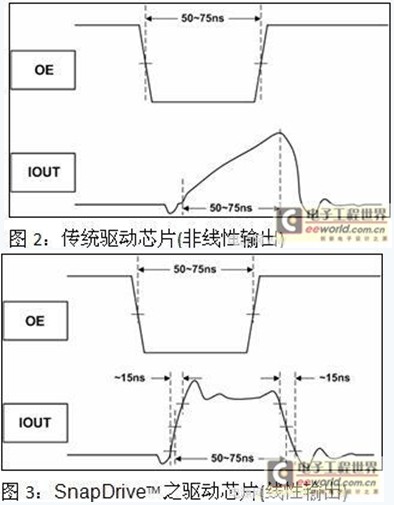
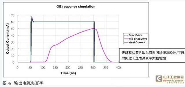
The following is the test conditions and results of the driver chip including SnapDriveTM technology introduced by Taiwan Xunjie Technology. It can be clearly seen from Fig. 1 and Fig. 3 that the output current of the driver chip is still linear output under the minimum OE pulse width, while the conventional driver The chip does not provide a linear output.
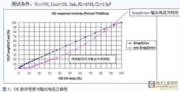
Test conditions: Vcc=5V, Iout=38.3mA, RL=47Ω, CL=13pF
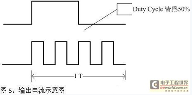
Reduced distortion rate for different output current slopes of the driver chip, using simulation software (HSPICE2007) we get different results in terms of distortion rate

Simulation conditions: traditional driver chip: Ton: 160ns, Tof: 70ns SnapDriveTM driver chip: Ton: 15ns, Tof: 15ns Vin: 5V, Iout = 20mA, LED equivalent circuit RL: 52Ω, CL: 10pf OE pulse width: 250ns
Solve the problem of LED heat and increase the life of LED. Figure 5 shows the current output of 50% Dutycycle. If the pulse of the current is evenly dispersed in the same time, it will not affect the output current and the brightness of the LED. Avoid LED lighting for a long time, causing LED overheating and early life attenuation.
Fast response circuit design uses a fast-responding driver chip to improve the gray scale and refresh frequency of the LED display; however, the formula ΔV=L•di/dt according to the inductance effect becomes smaller due to the time t; relatively instantaneous voltage change It is easy to produce a sudden wave. The author has listed several improvements in circuit design for readers' reference:
ΔV: the amount of change in voltage L: the inductance of the parasitic circuit on the circuit di: the differential dt to the current: the differentiation of time
There are a few points that need special attention in circuit design:
1. The PCB is preferably more than 4 layers, and the power supply and the ground are separated by one layer; the shorter the wiring, the better.
2. VLED and VCC add a large voltage regulator to the ground. It is recommended that CP1 and CP2 be 1000~1500uF.
3. VLED and VCC are separated into different power sources.
4. The RC circuit can be added to the frequency input terminal (Clock) to reduce its peak value and reduce the influence on electromagnetic interference. It is recommended that Rt<22Ω and Ct<33pF.

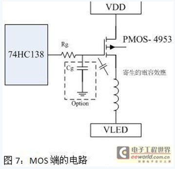
On the scan screen; it is recommended to string a resistor between the Gate end of the MOS and the 74HC138 to avoid the inductive effect of the VLED terminal and the surge caused by the parasitic capacitance of the MOS terminal, causing the 74HC138 to burn out; it is recommended that Rg<100Ω, Cg<47pF (capacitor section) You can choose not to add).
Conclusion: The fast response (SnapDriveTM) driver chip can not only improve the grayscale display and refresh frequency of the whole screen, but also reduce the current output distortion rate. Also, due to the long climb and fall time of the current driver chip, the set is not reached. When the current is constant, its nonlinear output will affect the LED's illuminating characteristics (wavelength), which may easily cause the display color distortion. However, due to the increase in transmission and operating frequency, designers must be more careful in circuit design. It is not only the method to select high-quality, high-reliability driver chips.
Related instructions:
OE: Chip Output Enable.
SnapDriveTM: A fast-responding driver chip developed and manufactured by Taiwan Xunjie Technology. The pin is fully compatible with TB62746 and other products.
All-in one Automatic Guling Technology, complete IP 68 waterproof.can be used under water , 3 years warranty.High light transmittance >97.7%, -20 to 80c working environment.Low-pressure molding, low-temperature solidfication for a better LED protection.Great Weather and UV resistance, anti-yellowing in 5 years.High-flexibility, anti-shock in different installation scenarios.Use the high quality smd leds,such as 2835,3014,5050,all leds are epistar chips inside,reliable package. Each led can be made into different colors,including the range of 2700K to 6000K,and also can do single color,such as red,green,blue,amber,purple etc.Many application place need the color changed,we can make dual color strips ,RGB strips as well.All-in-one led strips can be used indoor or outdoor application place,especially outdoor use because of his IP rating is 68.As everyone knows,we can't put the products underwater except they reaches IP68.All the products have passed CE,ROHS,FCC certification,they can be selled all over the world.
All-In-One Led Strip Light,Smd2835 Led Strip Light,Smd3014 Led Strip Light,Smd5050 Led Strip Light
Guangdong Kamtat Lighting Technology Joint Stock Co., Ltd. , http://www.ip68ledstrip.com