
Guide:
The price difference between the power inductor and the ferrite bead is significant, which drives the class D audio amplifier filter design into the era of no inductance. But at the same time, under the action of the ferrite bead, the cutoff frequency of the filter will rise sharply, increasing from a few kilohertz to several megahertz; thus weakening the EMI suppression effect of the filter. Therefore, Class D applications need to reduce EMI noise. In Class D audio inductive applications, achieving good EMI results depends on board level adjustment and proper PCB layout. The ferrite bead is equipped with a suitable capacitor to reduce the edge rate of the Class D output, but it also produces some transient oscillations that exacerbate the conducted electromagnetic interference. Therefore, it is necessary to use the Zobel circuit to reduce the instantaneous oscillation.
This article will introduce some board leveling techniques, including ferrite bead selection principles—reducing edge rates, Zobel network adjustment methods—reducing transient oscillations, and proper PCB layout. These solutions help customers significantly reduce system design costs while achieving superior audio performance by leveraging TI's latest EMI optimized Class D audio amplifier, the TPA3140D2.
Inductorless filter
The purpose of the inductorless design is to replace the expensive inductors with inexpensive ferrite beads to achieve a low-cost EBOM (Engineering Material Billing) goal at the system level. Ferrite beads are equivalent to multilayer chip inductors. Limited by current ferrite magnetic ring materials and manufacturing techniques, such inductors are difficult to withstand large currents and high impedance at the same time. Take the example of Japan's Toko Multilayer Chip Inductor. If the engineer sets the rated DC current value to "2.5A", most of the inductance value will be less than 1uH. Another product in the line, the Parallel Ferrite Bead Series (UPZ2012), has similar performance: if the maximum rated current is greater than 2.5A, the equivalent inductance of the ferrite bead is less than 0.6uH.
Table 1 shows the impedance of the UPZ2012 series ferrite beads at 100MHz, and the maximum rated current and maximum DC resistance of different ferrite bead rings.

As shown in Figure 1, the equivalent inductance of "120Ω@100MHz ferrite bead" is 0.39uH, while the 600Ω@100MHz ferrite bead has an equivalent inductance of 1.59uH. 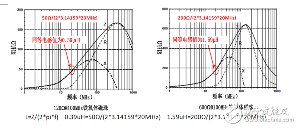
Figure 1 Ferrite bead equal inductance value
The ferrite bead works as a parallel resonant circuit, just as the inductor operates in the low frequency domain ("100MHz", the capacitor operates in the high frequency domain ("100MHz)), just as a pure resistor at its own resonant frequency point. When using an ferrite bead to set the output filter, the basis is to utilize its inductance characteristics. Since each LC filter (passive filter) has its own resonant frequency, at this frequency point, the gain of the filter is large, resulting in transient oscillation after filtering. R1 and C1 will absorb the oscillation energy caused by the IC itself, usually using a 10Ω resistor and a 330pF capacitor. R2 and C2 will absorb the oscillation energy caused by the filter itself.
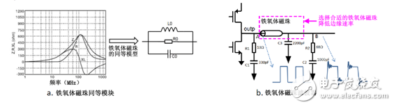
Figure 2 Ferrite bead filter design
How to use a non-inductive filter to achieve low EMI targets?
· Opinion 1: Select ferrite beads to reduce edge rate
Some techniques are used in TI devices to minimize the amount of EMI noise that is conducted in the 5MHz band, which is typically the cutoff frequency of the ferrite bead filter. The phase shift of the spread spectrum, L and R channels (Class D stereo audio) will also help. For EMI bandwidths less than 5 MHz, especially when the switching frequency is approximately 300 kHz (to achieve better efficiency), experimental results show that reducing edge rate is an effective way to reduce EMI.

Figure 3 Edge velocity of different impedance ferrite bead
In Figure 3, the higher ferrite bead impedance enables a lower edge rate Class D output; using a 600 ohm@100 MHz ferrite bead, the lowest edge rate Class D output can be achieved, ultimately at the high frequency band. Best EMI results. However, a higher impedance means that the rated current is smaller. In Table 1, the impedance is 600 ohm@100 MHz and the maximum rated current is 2A. Take TV customers as an example:
TV application example: PVDD (power supply) = 12V, speaker load = 8Ω, BD mode, ignoring the on-resistance and DC resistance of the PCB and ferrite beads. Maximum current = 12/8 = 1.5A.
In the case of PVDD = 12V / 8Ω speakers, engineers can use 600 ohm @ 100MHz ferrite beads to design the filter.
Figure 4 shows the effect of ferrite beads on conductive EMI
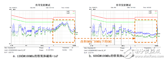
Figure 4 Effect of ferrite beads on conductive EMI
Figure 5 shows the effect of ferrite beads on radiative EMI

Figure 5 Effect of ferrite beads on radiative EMI
Opinion 2: Use the Zobel network to minimize transient oscillations.
Figure 6 shows a typical circuit we designed to reduce the oscillation effect of the output filter circuit. R1 and C1 will absorb the oscillating energy caused by the IC itself. R2 and C2 are used to absorb the oscillation caused by the resonant frequency of the filter.

Figure 6 Tuning to reduce oscillation and reduce edge rate
In Figure 7.a, in the conducted EMI test noise band, an oscillation of about 350 ns (about 2.85 MHz) is captured, and its energy has been greatly attenuated after the Zobel network, and a higher edge gain is obtained.
Table 2 Filter and Zobel Network Settings
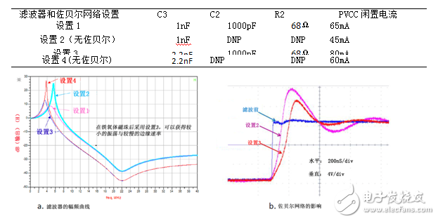
Figure 7 Adjusting the Zobel network and capacitors (reducing oscillations to achieve slower edge rates)
However, another problem arises. Figure 8 shows that the oscillations exacerbate the band noise of 2MHz~4MHz (if the class D output current increases, the oscillation will be more serious). In theory, the higher the harmonic component, the smaller the amplitude should be, but the resonant frequency point of the filter changes this. Let's take a look at Figure 7.a. Compared to setting 4, setting 3 has better noise rejection in the 2MHz~5MHz band. Finally, Set 3 shows the best tuning effect in reducing oscillations, and achieves a lower edge rate and a good EMI margin of 2MHz to 5MHz.
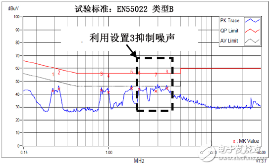
Figure 8 Oscillation aggravates 2MHz~4MHz band noise (Set 4)
PCB layout
Figure 9 shows the TI non-inductive Class D audio reference design board (TPA3140D2). Figure 10 is a schematic diagram of a typical output application circuit.

Figure 9 TPA3140 EVM board (left) saves a lot of filter PCB space 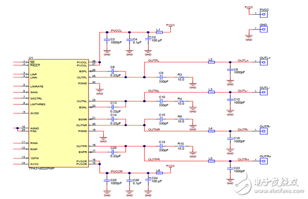
Figure 10 TPA3140 typical output application circuit schematic
l Filter PCB layout
To minimize the filter current loop (current back to GND), ensure that the current loop is small.
1) Place the ferrite bead as close as possible to the output pin.
2) Minimize the current loop of the filter ground (C8 to D ground pin)
3) Try to ensure that the bottom layer of the filter and Class D devices is a complete ground plane.
4) If you want to add a Zobel network to reduce the oscillation, place the Zobel network as close as possible to the filter.
5) Place the snubber circuit as close as possible to the output pin of the device.
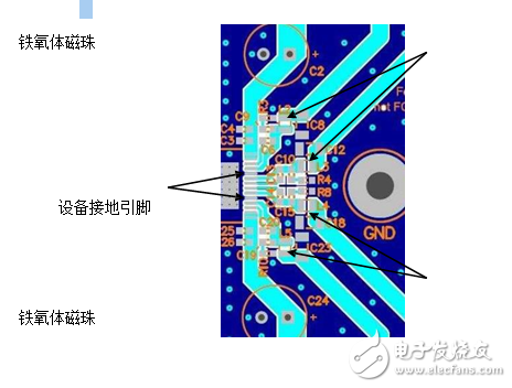
Figure 10 filter layout 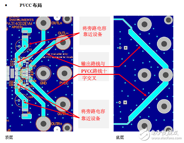
Figure 11 PVCC layout
in conclusion
TI's latest inductorless Class D stereo amplifier (TPA3140) enables inductorless designs to be implemented in medium power Class D applications. Depending on the speaker line length and output power (current) requirements, sound system engineers can use some of the board level tuning techniques discussed in this article, including ferrite bead selection principles (reduced edge rate), Zobel network tuning The method (reducing the oscillations) and the proper PCB layout, etc., finally enabled the TPA3140 to achieve sufficient EMI margin in the customer system level test. Feedback from current user designs shows that the TI TPA3140 is a true inductorless, medium power Class D audio amplifier that helps customers reduce system BOM cost, smaller PCB size, good EMC margin, and stable audio performance. The best balance is achieved.
Home Speaker System,Loud Party Speakers,Wireless Speaker System,Portable Party Speakers
Newmax Electronics Co.,LTD , https://www.fspeaker.com