At present, the programmable controller (PLC) selected by domestic users is still dominated by foreign products. An important reason for this situation is that developed industrial countries such as Europe, the United States, and Japan have mastered the core technology of high-end PLCs, and their hardware and software technologies. It is completely closed to the user. The user can only learn PLC from the perspective of application, but cannot participate in the development of PLC [1-2]. In recent years, the promulgation and implementation of the IEC61131-3 international standard has provided unified software development guidelines for PLC manufacturers. The development of open high-performance single-chip technology has provided an effective material basis for hardware development [3]. Against this background, the development of an open PLC system has positive practical significance for scientific research or for promoting the development of the PLC industry.
PLC is a computer dedicated to industrial control. Its hardware is mainly composed of central processor, memory, input / output interface, etc. [4]. Its hardware structure is shown in Figure 1.
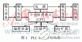
1 Open programmable controller
The open PLC hardware structure is composed of CPU + peripheral module + interface, and each interface is designed according to the standard, which greatly improves the openness of PLC and makes it easy to connect with large systems. The programming language follows the international standard IEC61131-3, and takes PC-based programming software as the PLC's preferred programming tool. The system hardware part adopts the high-performance 51 core processor STC89C51, which is a modular design, which uses filtering and isolation circuits to reduce costs. The main circuits are: microcontroller STC89C51RC, switch input circuit, relay output circuit, transistor output circuit, RS232 communication interface circuit, power supply circuit, clock reset circuit and USB communication interface circuit, etc. The PLC hardware system block diagram is shown in Figure 2. The software uses Borland's integrated development software C ++ Builder, which interprets and compiles the instruction set of the 51 core processor through the integrated platform, so that the ladder diagram language is converted into code that can be recognized by the 51 core processor.
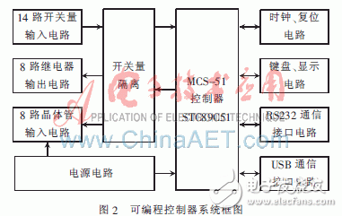
2 System hardware design
Part of the circuit diagram of the microcontroller of the programmable controller is shown in Figure 3.
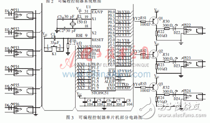
The USB communication part selects Philips' PDIUSBD12 [5] chip as the USB interface device of the system. The chip integrates a high-performance USB interface circuit, SIE, FIFO memory, transceiver and voltage regulator, etc., which can be used with any external controller or micro-controller. The processor realizes high-speed parallel communication at a rate of 2 Mb / s, which can fully meet the data transmission speed required by the design. The USB communication interface module circuit is shown in Figure 4.
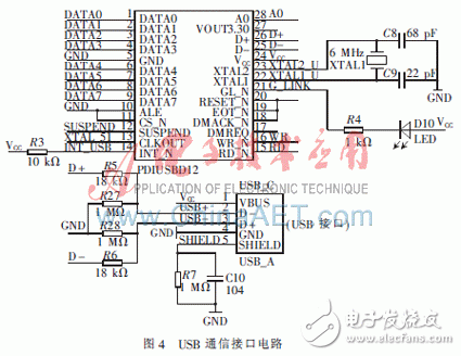
3 System software design
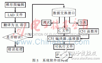
The system software structure is shown in Figure 5. In the figure, the system editing module provides an editing environment for the user, receives the user's ladder program input, and stores it as a corresponding file. The ladder diagram language is a graphical language, and it is very difficult to directly compile it. Therefore, instead of directly compiling the ladder diagram program, it is first translated into the text form of the instruction language, and then the instruction language is compiled. The resolution of the graphical language compilation problem has improved the code utilization [6-7]. By extracting the data in the data structure, a C language program file is formed, and through the compilation, connection, and conversion process of the C51 compiler, connector, and converter, an executable file that can be run on the PLC hardware is generated.
3.1 User interface
The PLC user interface is an important part of realizing programmable human-computer interaction. It enters the user control program in the form of ladder diagram language and downloads it to the PLC hardware through the serial port in binary form. The user programming area represented by the ladder diagram is shown in Figure 6.
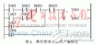
Before the PLC performs logical operations, it must sample the external signal [8]. To realize the function of the instruction, first, the address of the external I / O in the ladder diagram must be set, so that the system can use the I / O used in the user program. The O address matches the pin address of the microcontroller. This design has designed the data processing function shown in Table 1 at the bottom of the I / O settings dialog box.
3.2 USB communication
The firmware of PDIUSBD12 is designed to be completely interrupt-driven. When the CPU processes the foreground task, the USB transmission can be performed in the background; the data exchange between the background interrupt service program and the foreground main program loop can be achieved through the event flag and data buffer. When PDIUSBD12 receives a data packet from USB, it generates an interrupt request to the CPU, and the CPU immediately responds to the interrupt. In the interrupt service routine, the firmware moves the data packet from the internal buffer of PDIUSBD12 to the circular data buffer, and clears the internal buffer of PDIUSBD12 to receive new data packets, so that the CPU can continue to execute the current foreground task until completion . In this paper, the endpoint 1 of PDIUSBD12 is used for command transmission and response. The endpoint 1 receives the 8 B command sent by the computer each time, and the command format is shown in Table 2. For example, receiving the hexadecimal code 52 01 00 03 00 07 00 50 means reading 7 bytes of data from the 03 byte of the 24C01 device. 52H is the ASCII code of R, 57H is the ASCII code of W. Endpoint 2 is used for data transmission.
On the basis of understanding the research status of PLC at home and abroad and its market demand, this article puts forward the concept of R & D open PLC, completed the design of the C51 module implementation scheme of the PLC integrated development system, and introduced the USB communication method into the PLC field The ladder diagram editor provides a ladder diagram editing platform, realizes the basic logic instructions of the PLC, and completes the USB communication between the computer and the controller.
references
[1] Yang Jinzun. The characteristics and development trends of programmable controllers [J]. Modern Electronic Technology, 2007 (14): 1-2.
[2] Liao Changchu. The development trend of PLC [J]. Electric Age, 2003 (12): 54-56.
[3] ARC. China developing strategic strength in PLC market [J]. Plant Engineering, 2008, 62 (1): 14.
[4] Chen Liding, Wu Yuxiang, Su Kaicai. Electrical control and programmable controller [M]. Guangzhou: South China University of Technology Press, 2003.
[5] Zhou Ligong. PDIUSBD12 USB firmware programming and driver development [M]. Beijing: Beijing University of Aeronautics and Astronautics Press, 2006.
[6] Zang Guojie. Research and development of programmable human-computer interaction system [D]. Hangzhou: Zhejiang University, 2006.
[7] Guo Fushuai. Research and implementation of programmable controller based on IEC61131 standard [D]. Dalian: Dalian University of Technology, 2006.
[8] Qi Zhongwei. General PLC simulation and graphic programming system [J]. Mechanical and Electrical Engineering, 1998, 15 (1): 24-26.
Stainless Steel Electronic Cigarette Tube
Stainless Steel Electronic Cigarette Tube,Disposable Stainless Steel Electronic Cigarette Tube,High Precision Stainless Steel Electronic Cigarette Tube
ShenZhen Haofa Metal Precision Parts Technology Co., Ltd. , https://www.haofametals.com
