
Abstract: The long-distance radio frequency technology and single-chip technology are used to design the automatic bus station reporting system. When the RF card (bus stop) enters the working area of ​​the transmitting antenna (bus), the induced current is generated, and the energy obtained by the RF card is activated; the RF card transmits the information such as its own code through the built-in transmitting antenna of the card; the receiving antenna of the system receives the slave The carrier signal sent by the RF card is transmitted to the reader via the antenna adjuster, and the reader demodulates and decodes the received signal and sends it to the main system of the single chip microcomputer for related processing; the MCU recognizes the station identity after judging, and then correspondingly The voice information is read out through the speaker, thereby completing the automatic station reporting. The whole process requires no driver involvement, which not only reduces the driver's work intensity, but also ensures the safety of the bus and the accuracy of the station. The design has high practical value.
This article refers to the address: http://
0 Preface
At this stage, Global Positioning System (GPS) technology is becoming more and more mature, and more and more bus companies are using this technology to realize the automatic reporting of buses. However, this method is complicated in technology, large in investment, and difficult to promote. This paper uses remote radio frequency technology, combined with the working principle of single-chip microcomputer, to transform the manual station reporting device of the existing bus. Taking the practicality, cost performance and operability as the main starting point, we designed the automatic reporting system of the bus to reduce the labor intensity of the bus driver and improve the safety of the bus system and the accuracy of the station.
1 equipment overall design
The automatic bus station is mainly composed of RF reader, RF card, main control circuit board, voice storage module and keyboard display module. The block diagram of the design scheme is shown in Figure 1.
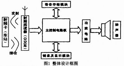
Set a specific RF card at the bus stop. When the bus enters the working range (the station enters the working distance of the antenna on the bus), the RF card on the station receives the signal from the transmitter and the information of the RF card. It is reflected back to the reader through the antenna. After receiving, it is verified by the MCU, and the signal is sent to the main control circuit for screening to identify the information of the station. After the identification is completed, the MCU activates the voice storage module, and calls the voice module to record the voice information corresponding to the station, and then uses the operational amplifier circuit to drive the sound in the bus to remind the passenger station information, so that the passenger rides more. Convenient, because the driver does not participate in the whole process, the safety of the bus is greatly improved.
2 Design of each component of the equipment
2.1 RF Transmitting and Receiving Circuit Design
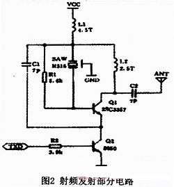
The RF transmitting part adopts the DF transmitting module, and its working frequency is 315MHz. The surface acoustic wave resonator is used for frequency stabilization, and the frequency stability is extremely high. It is especially suitable for multiple wireless remote control and data transmission systems. The DF data module has a wide operating voltage range of 3 to 12 V. When the voltage changes, the transmission frequency is substantially constant, and its emission distance becomes larger as the voltage increases. Through testing, the remote control distance is 30~50m away from the station, so the working voltage is set to about 3V, which can be adjusted according to the geographical location and environmental conditions of different stations. The transmitting part of the circuit is shown in Figure 2.
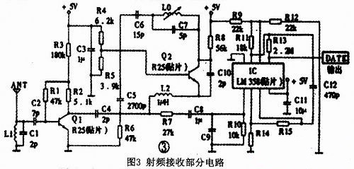
The RF receiving part still uses the DF module. The input antenna of the module has a frequency selective network, and the output has a waveform processing circuit, which can reduce the interference of the noise signal to the system. The module has very small radiation and the mesh is grounded on the back of the module. Copper foil reduces the effects of its own electromagnetic signal leakage and interference signals. The receiving part of the circuit is shown in Figure 3.
2.2 Control circuit design
The control core of this design adopts the 16-bit single-chip SPcE061A of Lingyang Company. The voice storage adopts SPR4096 chip of Sunplus Company. The keyboard and display adopt the keyboard and display module of Sunplus Company. The principle of the control circuit is shown in Figure 4.
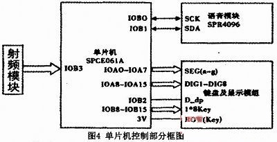
After receiving the signal reflected by the station, the RF receiver sends the signal to the microcontroller. The MCU performs station identification based on the stored station database, and then calls the corresponding voice message of the corresponding station recorded by the voice storage module after the identification is completed. The voice information is outputted by the digital-to-analog conversion circuit, and then the analog voice signal is output, and then amplified by the amplifier circuit to drive the speaker for voice broadcast, and the corresponding information is called to display the arrival information on the display screen. When the information of the station is abnormal, the bus driver can adjust the information of the station by operating the keys on the keyboard.
2.3 programming process
The programming flow is shown in Figure 5. First initialize the system to determine the initial location of the bus (default is from the starting station). During the operation of the bus, the radio frequency signal is continuously transmitted. When approaching the radio frequency card of a certain station, the identification test is first performed to check whether it is an interference signal. If it is an interference signal, the radio frequency signal is continuously transmitted, and if not, the reflected signal is returned. The RF signal is sent to the MCU for identification. The MCU program uses the query mode to identify the identity of the station, and then calls the corresponding voice information in the voice module and the station text information in the register to be sent to the audio and display for voice broadcast and display. The system installs manual control circuitry to address some special and unexpected conditions.
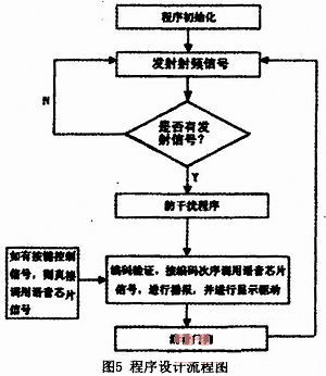
Next, the reflected RF signal is coded and verified, and the received RF signal code is compared with the code stored in the internal memory of the MCU, and the identity of the station is identified to determine the voice information in the calling voice module to ensure that it does not occur. The situation of incorrect reporting of the station can also solve the problem of mutual influence when multiple buses stop at the same platform (the bus RF readers of different roads are different). When there are some special and unexpected situations, the driver can press the control button to force the correction of the station program or make the bus send some specific voice information. After the accident is removed, the bus receives the new station signal, and after the code is verified, the program can resume automatic operation.
In the design process, this program considers the problems that may occur in the actual operation of the bus and meets the requirements of the system in actual operation.
3 Implementation of the design plan
In the automatic bus station reporting system, the original bus manual reporting system can be used to add a set of long-distance radio frequency equipment and a control single-chip microcomputer on the basis of the original. The control signal sent by the single chip microcomputer is added to the two ends of the button of the manual station by the photoelectric sensor. When the RF receiver receives the RF signal, the photoelectric sensor is driven by the single chip microcomputer to achieve the effect of the driver manually pressing the button, thereby reducing the automatic The cost of retrofitting the station system is more feasible. Considering that the roads and getting on and off the bus during the operation of the bus vary greatly, the driver's manual control circuit is still retained. In this way, if in some special cases, the driver can make corrections to the station system.
4 Conclusion
Through the actual test on the bus and platform, the bus automatic reporting system has achieved good transmission results. The system works stably, has excellent performance, low cost, and has strong practicability and promotion value. It can be used to transform the existing bus manual station device on a large scale.
Roof De-Icing Heat Film is mainly for Snow Melting Mat,Anti-Freeze,Reduce risk and save time by installing snow & ice melting systems on your roof or gutters,snow melting around chimney,snow melting fast on roof,snow melting ideas,snow melting machine used in boston,snow melting materials,snow melting salt replacements,snow melting services,roof gutter de-icing kit,roof de-icing system,roof de icing products.mats,flat roof de icing system,roof deicing tape,heat roof snow de-icing kit,flat.metal roof de-icing,diy roof de-icing,thermal technologies roof de icing system,easy heat roof de icing,Melting Snow on your roof ,prevent damage for your house,It's economical for Infrared heating film for roof heating.It's Simple to install and move.It is easy to clean and portable.we are a professional and leader Chinese exporter of heat film,Customization options(for example: SMT components,flex cable and connectors) can provide the perfect complete solution that can significantly reduce assembly time and increase productivity.Providing a variety of complex shapes design,and different power designs. Membrane in the same piece electrically heated heating circuit can be designed and holding circuit,we are looking forward to your cooperation.
Snow Melting Heat Film For Roof Protection
Roof Heat Film, Snow Melting Heat Film,Snow Melting Pad For Gutters,Snow Melting Salt Replacements Heater
ShenZhen XingHongChang Electric CO., LTD. , https://www.xhc-heater.com