
Abstract: A data acquisition and control system for accurate measurement and timely control of various water valves, dampers, variable air volume boxes, electric heaters, humidifiers and other control components is established in the HVAC system. Use NI LabVIEW Developer Suite to unify the various devices in the HVAC system for centralized acquisition control. Establish a PC-based HVAC data acquisition control system.
introduction
LabVIEW is widely used in the field of automatic control. It is rare to use LabVIEW as the upper-end software in HVAC systems. However, with the release of LabVIEW 7 Express, LabVIEW has gradually penetrated into various fields. After using LabVIEW in the professional HVAC automatic control field, I found that it is very powerful and saves system development time, which is very suitable for engineering developers. The author combines a recent HVAC system to introduce the application of LabVIEW in HVAC data acquisition and control system.
1 overall system structure
There is a large amount of data in HVAC that needs to be collected, and various system parameters are adjusted by collecting data. The system is mainly composed of a water system, a wind system and a control system.
â— Water system includes: water-cooled chiller, cooling tower, expansion tank, chilled water pump, cooling water pump, three-way control valve, flow meter and other accessories.
â— The wind system includes: combined air conditioning box, air supply duct, return air duct, exhaust duct, VAVBOX, valves and other control components. The air conditioning box includes a new return air mixing section, a filter, a surface cooler, an electric heater, a blower fan, a steam humidifier, and the like. Fan inverter control. The new return air duct is equipped with electric regulating valves, which can adjust the proportion of new return air. The front and rear of the air cooler are equipped with temperature and humidity measuring points. The air conditioning box is also equipped with nozzles for air flow measurement.
â— The control system includes: pressure sensors, temperature sensors, control components, actuators, data acquisition devices, computers, touch screens, etc., for automatic detection and data processing of the built environment and equipment.
There are two rooms in the experimental system: Room1 and Room2. Room1 is mainly used to establish a low temperature environment laboratory, so it is equipped with a direct evaporative water cooling unit. Each room has a load generator Ld for generating simulated loads and temperature and humidity points. In Room1, a set of return air outlets is arranged, and the lower side is sent back; in the Room2, two sets of return air outlets are arranged, which are top sending and side returning respectively. Each delivery and return air port is equipped with a manual regulating valve that can be switched or adjusted. A differential pressure sensor is placed in the room to control the positive pressure in the room. A pressure independent VAVBOX is installed on the air supply ducts of the two rooms.

Through the schematic diagram of the system of Figure 1, everyone can have an intuitive understanding of the system.
2 data acquisition control system
The system is divided into two parts: data acquisition and system control. The data acquisition part has various data acquisition devices. The control section is completed by a PLC (Programmable Controller). LabVIEW can easily operate the serial port of the computer. Therefore, LabVIEW can easily establish communication between the serial port of the computer and the serial port of the PLC, conveniently obtain the data in the PLC, perform complex operations such as PID neuro-fuzzy in the computer, and thus obtain the required Digital control signals that control the devices that need to be controlled to enhance the versatility of the system. And can develop more rich features. The hardware and software parts used in the entire data acquisition system and the relationship between them can be seen from Figure 2.
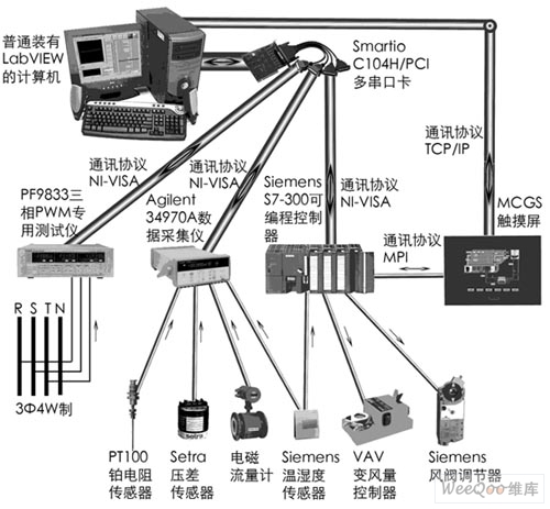
Figure 2 Acquisition control relationship diagram
The data available through the data acquisition system are: water cooler flow, VAVBOX1, 2 air volume feedback, air supply humidity, fresh air temperature and humidity, low greenhouse wall-mounted temperature and humidity meter temperature and humidity, variable frequency compressor before and after throttle, nozzle pressure difference , dry and wet bulb temperature before and after the cooler, suction and exhaust temperature of the evaporator unit compressor, intake and exhaust temperature of the inverter chiller compressor, intake and exhaust temperature of the chiller compressor, inlet and outlet temperature of the cooler, hot water inlet Temperature, cooling tower inlet water temperature, variable frequency chiller cooling inlet and outlet water temperature, variable frequency chiller inlet water temperature, chiller cooling water inlet and outlet water temperature, chiller inlet and outlet water temperature. It can be seen that a large number of different sensors need to be set.
The end sensors used are: PT100 platinum resistance temperature sensor. The platinum resistance uses four-wire system to improve the measurement accuracy and avoid the influence of the data line resistance along the way. The EE10 indoor temperature and humidity transmitter generates a standard current signal of 4 to 20 mA. In order to facilitate the data acquisition instrument to measure and avoid signal distortion, a 250Ω precision resistor is added to convert the current signal into a standard 1~5V voltage signal. . The pressure sensor, damper opening controller, humidity and other signals are standard 1~5V standard signals, or converted to 1~5V standard signals, which is convenient for data acquisition instrument processing. These signals are linear or approximately linear and can be converted to our familiar temperature and humidity pressure values ​​by gain and offset (M x B). For example, the acquired signal is 3V. At this time, 1V corresponds to 0°C, and 5V corresponds to 100°C.
Y=MX+B
Calculate M=25, B=-25, and then substitute 3, and get Y=50°C. This section is easy to convert signals by using LabVIEW's Database Toolset toolkit and global variable data exchange.
Data acquisition instrument: The standard signal generated by the sensor and transmitter directly enters the data acquisition instrument. The data acquisition instrument uses the Agilent 34970A data acquisition instrument (with three HP 34901A 20-channel armature relay multiplexers). It can directly measure thermocouples, resistance temperature testers, thermistors, DC voltage, DC current, AC current, etc. The supply current, voltage, power and frequency are measured by the PF9833 three-phase PWM dedicated tester. By using the NI-VISA protocol, the serial port read and write operations can be easily performed, as shown in Figure 3.
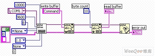
Figure 3 NI-VISA serial port read and write in LabVIEW
The communication between the control system PLC and the PC is also communicated using the NI-VISA protocol. By writing the command request to the serial port, the device analyzes and recognizes the command, returns the data requested by the command to the computer through the RS-232 interface, and then reads the data through the serial port (Read) to obtain the data collected by the device. There are no commands for different devices. The Agilent 34970A uses the SCPI (Standard Commands for Programmable Instruments) programmable instrument standard command set. The PF9833 uses an additional command set. Regardless of the protocol used by different devices, it is easy to establish communication between the device and the computer through NI-VISA. For the PLC, you need to write a device-side program. After the program is required to obtain the command, the command is analyzed and identified, and the corresponding data is sent out.
The signal control uses Siemens SIMATICS7-300 PLC, and some of the control signals that affect the control enter the PLC, perform PID analysis and calculation, generate control signals, and control the dampers, fans, pumps, heaters, etc. The PLC has an RS-232 communication interface to establish communication directly with the computer. The PC obtains various signals entering the PLC, and can also perform more complicated calculations in the computer, generate digital control signals and return them to the PLC, and then the PLC controls various devices that need to be controlled.
The system can issue control commands to the whole system through the touch screen. Each switch of the touch screen corresponds to each switch contact of the PLC, which is equivalent to the keyboard of the PLC, and can adjust various parameters of the whole system. For example, the switch of the damper, the start and stop of the fan, the water pump and the electric heater, and the setting of the three parameters of the PID control devices P, I, D (proportional, integral, differential) can be operated accordingly, and the system flow chart can be clearly defined. Reflected from it.
Since a large number of serial ports are used for data communication, a multi-port serial card is needed to connect multiple serial devices.
3 LabVIEW program
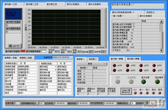
It is easy to design a beautiful and beautiful user interface through LabVIEW graphical design. See Figure 4 below. When using the Agilent 34970A data acquisition instrument, it can measure various parameters such as temperature, voltage and current. When collecting, it involves the need to change the parameters.
Using NI's Database Connectivity Toolset, edit the parameters of the changed acquisition channel directly in an already edited database (Hpsetting.mdb), and then choose whether to download the new settings to the data when running the program. The acquisition instrument changes the corresponding settings of the data acquisition device to collect the correct data. Setting parameters include channel number, channel description, input type, range, period, delay, trigger, platinum resistance and calibration. As long as the data is collected using the Agilent 34970A data acquisition instrument, the program does not require major modifications, saving development costs and time, and improving program versatility.
The NI PID toolkit is used for control, and PID control can be performed on the parts that need to be controlled. This toolkit can save us a lot of development time. A big feature of LabVIEW is that it provides a large number of available controls. The control provides input and output. By inputting data through a line connection, it is convenient to get the required control commands from the output port.
4 experiment
LabVIEW works with a variety of sensors in many systems and plays a big role in system debugging. The required data can be displayed on a computer with a normal LabVIEW. The data in the debug is analyzed and displayed using LabVIEW to see if the system meets the predetermined requirements.
LabVIEW software is used in the system and there are no need to make too many changes on the hardware. The required measurement control parameters have been set in the system debugging phase, and only work on the software interface and various parameter combinations.
In the data acquisition and control experiment of the chiller, the interface is shown in Figure 4. The air conditioning system is turned on, and the current temperature and humidity signal is obtained through the data acquisition device. Obtain the data through the PID operation, output the control signal, and finally adjust the PID parameters (change the PID parameters in the interface, through the PC to the PLC control, to achieve the purpose of the control device) so that the temperature and humidity parameters are finally stable near the set value, The purpose of experimental control was achieved. Finally, the data saved in the experiment can be printed as a report through NI's Report generation toolset.
The hardware does not need to be adjusted, mainly in software editing (LabVIEW is a graphical language). Because the development time of the software is shortened, the development time of the entire data acquisition control system is also greatly shortened.
5 Conclusion
LabVIEW has great advantages in system development. From the perspective of system construction time, using LabVIEW for software programming and PLC programming of the same system takes less time and the program interface design is easier and more beautiful. Programming with PLC and making it visible through the visual interface (we use the MCGS embedded graphical interface here) is the work that both systems need to design. LabVIEW combines both, and you can program LabVIEW with a simple PC, and finally develop the interface and functions we need in a short period of time, until the final product. The use of LabVIEW not only has obvious advantages in time, but also has great advantages in system redevelopment. If the system needs to develop a new functional project, add a sensor measurement component to the system for signal measurement, and then design the interface analysis display in LabVIEW to quickly achieve the desired result. LabVIEW is the best choice for the system that I need to continuously improve. (Author: University of Shanghai for Science and Chen Qian Wengwen Bing)
references:
[1]. PLC datasheet http://
[2]. PT100 datasheet http://
[3]. EE10 datasheet http://
[4]. RS-232 datasheet http://
:
Vibration Motor is in the original basis to add a vibrating head, made into a Dc Motor drive with a vibration motor. To produce the shaking force.
6V Dc Vibration Motor is introduced:
6V Dc Vibration Motor volume is generally greater than 15 mm, mainly used in massage chair, massage waist, handheld massager, etc.
Characteristics: small volume, strong vibration;
Features: small size, fast speed, stable performance, low price, can use battery drive,Can change the different materials of the pendulum head


Method of use: the best stable in horizontal plane, installed on the dc 6V Dc Vibration Motor output shaft parts, cannot use a hammer to knock, knock prone to press into the dc 6V Dc Vibration Motor drive, may cause damage to internal components, and cannot be used in the case of blocked.

Operating temperature range:
6V Dc Vibration Motor should be used at a temperature of -10~60℃.
The figures stated in the catalog specifications are based on use at ordinary room temperature catalog specifications re based on use at ordinary room temperature (approximately20~25℃.
If a vibration motor is used outside the prescribed temperature range,the grease on the gearhead area will become unable to function normally and the motor will become unable to start.Depending on the temperature conditions ,it may be possible to deal with them by changing the grease of the motor's parts.Please feel free to consult with us about this.
Storage temperature range:
Dc Vibration Motor should be stored ta a temperature of -15~65℃.
In case of storage outside this range,the grease on the gearhead area will become unable to function normally and the motor will become unable to start.
Service life:
The longevity of Dc Vibration Motor is greatly affected by the load conditions , the mode of operation,the environment of use ,etc.Therefore,it is necessary to check the conditions under which the product will actually be used .The following conditions will have a negative effect on longevity.Please consult with us should any of them apply.
â—Use with a load that exceeds the rated torque
â—Frequent starting
â—Momentary reversals of turning direction
â—Impact loads
â—Long-term continuous operation
â—Forced turning using the output shaft
â—Use in which the permitted overhang load or the permitted thrust load is exceeded
â—A pulse drive ,e.g.,a short break,counter electromotive force,PWM control
â—Use of a voltage that is nonstandard as regards the rated voltage
â—Use outside the prescribed temperature or relative-humidity range,or in a special environment.
â—Please consult with us about these or any other conditions of use that may apply,so that we can be sure that you select the most appropriate model.
when it come to volume production,we're a major player as well .each month,we rurn out 600000 units,all of which are compliant with the rohs directive.Have any questions or special needed, please contact us, we have the engineer group and best sales department to service to you Looking forward to your inquiry. Welcome to our factory.

6V Dc Vibration Motor
6V Dc Vibration Motor,Dc Vibration Motor,6V Dc Micro Vibration Motor,Small Size 6V Dc Vibration Motor
Shenzhen Shunchang Motor Co., LTD. , http://www.scgearmotor.com