
As high-fidelity audio systems become larger and more power-hungry, the redesign of Class D audio amplifiers will meet the unique challenges of automotive audio design. For automotive information and infotainment systems, the number of functions and subsystems is increasing, and the audio power budget requirements for the front and the body of the car have reached the limit. Car audio designers are looking for high-performance, low-cost solutions. For many applications, ultra-efficient Class D amplifiers may be the best choice.
Especially for high-end cars, multi-channel, multi-speaker systems have become standard equipment. The design challenges faced by car audio engineers include: maintaining or exceeding customer expectations for extremely high sound amplifier levels and ultra-low distortion; and requiring higher power in response to the trend toward dual or even three-channel speaker systems and heavy bass. design.
Unlike audio amplifiers in home entertainment systems, design engineers cannot simply increase power and find a way to control the quality of the audio to meet these goals. The space under the driving dashboard is very limited and does not allow for a lot of heat. In addition, the power supply voltage in the vehicle is also limited, and there are often voltage abnormalities caused by such as voltage jumps and interference from other electronic and mechanical systems in the vehicle.
Each new model adds new subsystems to the sound design, such as video or even navigation and GPS. As a result, the sound system is faced with more speakers, more channels, and higher power requirements. Under normal circumstances, the space left for the audio drive system is more cramped.
The demand for audio power has been increasing. There are two basic ways to meet these needs. The traditional way is to add more channels driven by standard audio amplifiers. This scheme is employed in an active system where each amplifier drives a speaker. But because of the increase in the number of channels, this approach has become more complex and increasingly difficult to sustain.
Another method is to increase the power output by reducing the impedance of the speaker or by using a DC/DC converter to increase the supply voltage. With this method, a single amplifier can drive two or three speakers and still get high-fidelity audio output.
Although the second solution is less complex, the two solutions still have a common point: they all increase the power consumption. Therefore, to meet power consumption metrics, the adoption of more efficient systems is the key to a specific solution.
The need for more efficient amplifiers has made the discussion of Class D audio amplifiers a hot topic among audio designers.
Class D audio is up to 95% efficient, while Class AB audio amplifiers are only about 50% efficient; therefore, Class D audio amplifiers provide superior sound quality while maintaining power consumption. The good power efficiency of Class D audio amplifiers means that they require only a smaller heat sink, saving space for a narrow front unit to accommodate more electronic systems. However, Class D is much more expensive than Class AB amplifiers and requires special design considerations.
Figure 1 shows the relative efficiencies of Class AB amplifiers (Figure 1a) and Class D audio amplifiers (Figure 1b) over the output power range.
This article refers to the address: http://
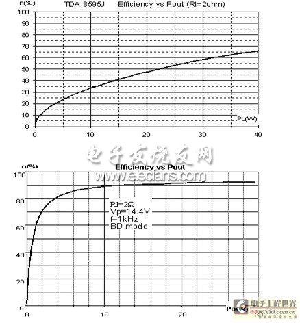
Figure 1 In a wider range, Class D audio amplifiers have higher efficiency. Remember that these two methods are not incompatible. In fact, innovative engineering often uses a hybrid approach. Car audio is no exception. Design engineers will make decisions based on the following key considerations:
The size, power requirements and cooling capacity of the front unit The cost of the sound system reduces the interference from other electronic and electromechanical equipment.
1 The technical basis of the amplifier is to fully understand the Class D audio amplifier. We will first briefly introduce the technical basis of the amplifier.
The output components of the Class A amplifier are continuously turned on throughout the cycle. In other words, the bias current flows all the way through the output components. Class A amplifiers have the best linear output with minimal distortion. But the disadvantage is that the efficiency is too low, only about 20%.
The output components of the Class B amplifier are turned on during the half cycle of the sinusoid (one in the positive half and the other in the negative half cycle). If there is no input signal, no current flows through the output component. At the maximum output power, Class B amplifiers have the highest efficiency of 78.5%. However, the spacing between the closing of one output element and the conduction of the other output element creates a linear problem at the intersection.
Class AB amplifiers are combinations of the two types described above. The two components are simultaneously turned on near the intersection (although very close). The on-time of each component is longer than half but shorter than one cycle, overcoming the nonlinearity of the Class B amplifier design. Class AB amplifiers have an efficiency of approximately 50%. It is the most commonly used power amplifier.
Class D audio amplifiers are switching and pulse width modulation (PWM) amplifiers. Since the switch is not fully open or fully closed, the loss on the output component is greatly reduced. It is said that its efficiency can reach 90~95%. The audio signal can be used to drive the PWM carrier signal of the output component. However, since the Class D audio amplifier is a switch type, it generates switching noise. The final stage is a low-pass filter that filters out the high frequency PWM carrier frequency.
2 Class D and Class AB amplifiers Class AB amplifiers are currently the standard in automotive audio applications. The technology is very mature, so it is relatively easy to develop products and does not require adjustments and re-entry. The fierce competition among many IC manufacturers has also made the price of Class AB amplifiers reasonable. Since Class AB amplifiers require only a few external components, the cost of raw materials is further reduced. In addition, Class AB amplifiers have the advantage of not generating electromagnetic interference (EMI) when compared to the original Class D audio amplifier.
Disadvantages of Class AB amplifiers include relatively high power consumption and heat generation caused by 50% efficiency, but these shortcomings become a serious problem only when the sound system becomes more complex. However, in the application of the front unit, the class AB amplifier has caused a new problem: due to the increasing power consumption, when the power supply voltage is higher than 18V, it is impossible to generate higher output power with the class AB amplifier.
In addition to 90% efficiency, Class D audio amplifiers can be designed to interface with digital signal processors (DSPs) that process audio, saving the cost of integrating an analog/digital converter within the DSP. (Class AB amplifiers have a basic analog connection; however, it is not appropriate to refer to Class D audio amplifiers as 'digital' amplification.) Finally, Class D audio amplifiers can be integrated into 60V power lines.
3 Six-channel design example Currently, many production models have 4 channels and 8 speakers. In addition, the amplifier must be able to support the entire audio spectrum, and the bass and mid-tone speakers usually share the same channel and amplifier. A smattering of this 4-channel configuration will likely resonate at the door (see Figure 2).
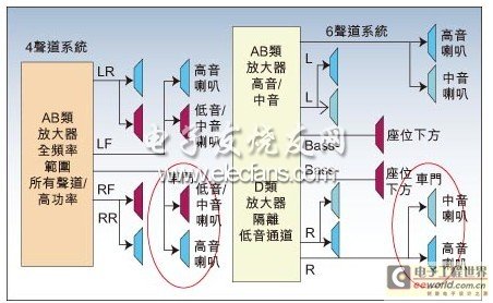
Figure 2 Comparison of 4-channel and 6-channel audio architecture
Adding two channels will solve several problems. First, it allows the high-powered woofer to be driven independently with two new channels to eliminate door resonance. In addition, since all speakers do not have to work over the entire frequency range, it is possible to achieve high-fidelity sound quality.
But as every car audio designer puts it, the space and heat restrictions make the front unit power consumption not higher than 20W. The traditional practice of circumventing this problem is to drive some of the speakers with an external amplifier unit placed on the body. Although feasible, the program also adds to the overall system complexity and cost.
The wise use of Class D audio amplifiers provides a cost-effective answer to this problem. Based on the normal amplifier value, an efficiency of 55% Class AB amplifier consumes 4.5 W, while an efficiency 94% Class D audio amplifier consumes 0.6 W.
The use of six Class AB amplifier channels will result in a total of 27W of power consumption, which is 7W higher than the power consumption normally considered by the front unit (see Figure 3, Case A). However, if you combine Class AB and Class D audio amplifiers, you will be able to meet your power budget even with only two Class D audio amplifiers (most likely for woofer drivers). The bottom line of Figure 3 shows the overall power consumption difference of 20W from this particular configuration.
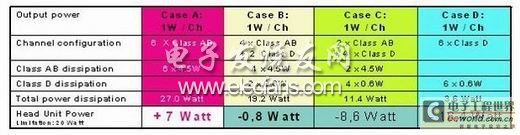
Figure 3 uses only two Class D audio amplifiers to provide a 6-channel system with an ideal price/performance ratio. The cost of a Class D audio amplifier for the front unit is likely to make Case B the most likely choice for mid-range models. But looking to the future, especially in the case of the 'Quality Sound System' market (higher power rating), Class D audio amplifiers are likely to expand their market share.
The high-end car audio system may support a minimum of 8 channels and up to 22 channels, many of which will be placed in the body unit. If a Class D audio amplifier is not used in the system, supporting multiple channels may be almost impossible.
In the ongoing trade-off between cost and quality objectives, design engineers will find many combinations of Class AB and Class D audio amplifiers. Class D audio amplifiers will initially find use in applications where low power consumption is critical and (somewhat unexpectedly) requires high power output. These applications include systems with power greater than 90W, with stereo Class D audio amplifiers being the best choice. But its applications can be categorized into four systems:
High-order: 8- to 22-channel system driven by a combination of Class AB and Class D audio amplifiers, with power greater than 28W per channel.
Mid-range sound system optimized for power consumption: 4 to 6-channel system driven by a pure Class D audio amplifier with more than 25W per channel.
Mid-range sound system optimized for cost: 4- to 6-channel system driven by a combination of Class AB and Class D audio amplifiers.
Basic sound system: 2 to 4 channel system driven by Class AB amplifier, less than 28W per channel.
4 Class D amplifier automotive environments for automotive applications present challenges for Class D audio amplifier applications. To design a superior product, semiconductor suppliers must provide their knowledge, skills, and extensive experience with Class D audio amplifiers and automotive applications.
For starters, I2C control has been incorporated into the needs of automotive design. In addition, the challenge is becoming more difficult. For example, the output voltage of a Class D audio amplifier is affected by the power supply voltage, and the power supply voltage in the vehicle is unstable. Several measures have been taken to suppress the supply ripple voltage. The best way to suppress voltage fluctuations is to use a negative feedback loop. A second order feedback loop provides excellent ripple rejection.
The EMI caused by the switch is one of the most serious problems of the Class D audio amplifier and is very difficult to solve. At the design level, EMI can be mitigated by phase staggering, frequency hopping, and AD/BD modulation.
Increasing the EMI surge current is caused by the dead time introduced between the internal transistors when the amplifier is switched. During the dead time, current accumulates on the body diode and the charge is bleed as a current surge (shown in Figure 4, the red line indicates the glitch).

Figure 4 Current surge introduced by dead time generates EMI
Eliminating dead time is an obvious solution. To achieve this goal, NXP has resorted to its semiconductor manufacturing expertise. Since all elements of the overlying silicon dioxide (SOI) on the insulating layer are insulated by oxide, SOI is an ideal technique. When the output voltage is lower than the ground voltage, there is no charge accumulation in the element base layer, which shortens the reverse recovery time and has no crosstalk with other channels.
5 Summary Class D audio amplifiers will expand their market share in car audio applications. By 2015, it will account for 30% of the automotive amplifier market.
As Class D audio amplifiers enter automotive applications, NXP will not only go hand in hand with this trend, but will also lead the trend.
Yamaha Feeder , original and new or used feeder, in stock.
Material: Stainless steel
Feeder can be divided into tape feeder, tube feeder, tray feeder or stick feeder.
Feeder can be divided into original feeder and replacement feeder.
All the feeders shall be maintained during the use time
YAMAHA SS 8mm ELECTRIC feeder KHJ-MC100-000,
YAMAHA SS 12mm ELECTRIC feeder KHJ-MC200-000,
YAMAHA SS 16mm ELECTRIC feeder KHJ-MC300-000,
YAMAHA SS 24mm ELECTRIC feeder KHJ-MC400-000,
YAMAHA SS 32mm ELECTRIC feeder KHJ-MC500-000,
YAMAHA SS 44mm ELECTRIC feeder KHJ-MC600-000,
YAMAHA SS 56mm ELECTRIC feeder KHJ-MC700-000,
YAMAHA SS 72mm ELECTRIC feeder KHJ-MC800-000,
YAMAHA SS 88mm ELECTRIC feeder KHJ-MC900-000,
YAMAHA ZS 8mm ELECTRIC feeder KLJ-MC100-000
YAMAHA ZS 12mm ELECTRIC feeder KLJ-MC200-000
YAMAHA ZS 16mm ELECTRIC feeder KLJ-MC300-000
YAMAHA ZS 24mm ELECTRIC feeder KLJ-MC400-000
YAMAHA ZS 32mm ELECTRIC feeder KLJ-MC500-000
YAMAHA ZS 44mm ELECTRIC feeder KLJ-MC600-000
YAMAHA ZS 56mm ELECTRIC feeder KLJ-MC700-000
YAMAHA ZS 72mm ELECTRIC feeder KLJ-MC800-000
YAMAHA ZS 88mm ELECTRIC feeder KLJ-MC900-000
YAMAHA FT feeder 8×2mm KJW-M1100-023,
YAMAHA FT feeder 8×4mm KJW-M1200-023,
YAMAHA FS2 feeder 8×2mm KJK-M1300-011,
YAMAHA FS2 feeder 8×4mm KJK-M1500-011,
YAMAHA CL feeder 0201mm KW1-M1500-030,
YAMAHA CL feeder 8×2mm KW1-M1300-000,
YAMAHA CL feeder 8×4mm KW1-M1100-000,
YAMAHA CL feeder 12mm KW1-M2200-301,
YAMAHA CL feeder 16mm KW1-M3200-100,
YAMAHA CL feeder 24mm KW1-M4500-015,
YAMAHA CL feeder 32mm KW1-M5500-000,
YAMAHA CL feeder 44mm KW1-M6500-000,
YAMAHA CL feeder 56mm KW1-M7500-000,
YAMAHA CL feeder 72mm KW1-M8500-000,
YAMAHA CL feeder 88mm KW1-M9500-000,
In addition, the following products can be found in our company.
Yamaha Smt Feeder
YAMAHA Feeder
Smt Feeder For Yamaha
Siemens Smt Feeder
Siemens Feeder
Samsung Smt Feeder
YAMAHA Feeder
Yamaha Feeder,Yamaha Smt Feeder,Smt Machineyamahafeeder,Smt Feeder For Yamaha
Shenzhen Srisung Technology Co.,Limited , https://www.sr-smt.com