
Introduction
This article refers to the address: http://
This article will focus on the design techniques and related challenges of implementing electric bicycles using microcontrollers or programmable system-on-chip (PSoC). The current industry's electric bicycle system uses a microcontroller and external signal conditioning and comparator circuits to drive three-phase motors; an external ADC and an external amplifier to support different sensor inputs; and a relay drive circuit to support brake lights, headlights, and turn signals; It also supports LED/LCD displays and temperature measurements.
Programmable SOC devices can be used not only as a unified circuit board system for motor control, analog measurement, and direct drive LCD displays for electric bicycle applications, but also to support capacitive sensing technology to replace mechanical buttons on the keyboard. In addition, SOC devices can use internal PWM, MUX, and comparators to drive and control three-phase motors, internal ADC and PGA to support sensor input battery monitoring, and temperature sensing devices such as thermistors or RTDs for temperature sensing. The device not only directly drives the relay to support brake lights, headlights and turn signals, but also directly drives the LCD display to display temperature, battery status, speed, ride distance and various error/warning messages.
Using IDE-based tools, you can design a variety of interfaces and logic for SoCs. These tools also provide directly available component modules for designing more complex logic such as capacitive sensors for monitoring interfaces, ADCs that support analog sensors and other inputs, PWMs, DACs that drive buzzers, and segments, characters. Or a graphical LCD display, etc. Therefore, with the programmable SOC, the development and production cost of the electric bicycle system can be greatly reduced.
Figure 1 shows a block diagram of a basic electric bicycle system:
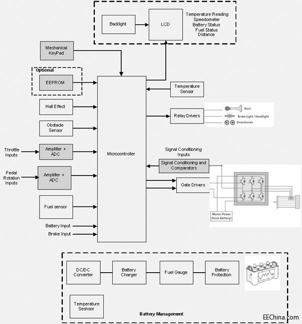
Figure 1: Block diagram of an electric bicycle
Microcontrollers: Microcontrollers are commonly used for different sensor input detection (eg throttle input, temperature sensor, battery input, fuel sensor, barrier sensor, etc.), analog to digital conversion, output comparison components, etc., and can be driven and controlled. No brush motor. Battery-powered electric bicycle systems require ultra-low power microcontrollers. In addition, the microcontroller is part of a central locking system that can be used to communicate with a variety of different external devices used in vehicles. Whenever braking, the microcontroller can be used to automatically stop the motor from rotating, thus avoiding the motor wearing brake pads faster than standard human bicycles.
Hub Motor: Normally, brushless motors can be used for efficient and reliable operation, with or without sensors (based on Hall effect).
Rechargeable lead-acid/lithium-ion batteries: Electric bicycle applications range from lead-acid batteries to lithium-ion batteries. Among them, rechargeable lead-acid batteries are widely used in electric vehicles.
Display and keyboard: In general, the LCD display with backlight can display temperature, battery input, speed, riding distance and error/warning messages, as well as the level of the pedal assist system and energy generation. . Electric car applications also use a keyboard based on mechanical buttons, and the keyboard can also support the anti-theft function of electric vehicles.
Power Management: This subsystem provides power to the operation of each functional module and monitors battery operation. A host microcontroller with comparators and discrete logic can be used to manage lead-acid batteries. In addition, this approach provides microcontrollers and users with safety and critical information about the battery.
principle
Current electric bicycle systems use 16-bit and 32-bit microcontrollers. The microcontroller controls and manages all the functions and features of the vehicle. Once the user turns on the ignition switch and starts the electric bicycle, the microcontroller can obtain input to start the three-phase brushless motor. The microcontroller can receive various vehicle input signals from the user and perform corresponding manipulations on the vehicle. The microcontroller drives the three-phase brushless motor at a speed selected by the user. The speed of the motor can be varied and controlled based on the user's acceleration and brake sensor inputs.
The microcontroller uses an internal or external serial EEPROM (I2C/SPI type) to store data such as distance readings. In addition, the microcontroller uses a real-time clock (RTC) to display accurate time on the display.
Temperature measurement is achieved by on-board RTD or thermistor type temperature sensing devices. The electric bicycle system can also use the obstacle sensor to obtain information about nearby vehicles while parking. The fuel sensor acquires fuel information from the engine, and the microcontroller can also monitor the battery input and display it on the LCD display. The relay drive circuit is used to switch the brake lights, headlights, and turn signals on/off.
The power supply section consists of a rechargeable lead-acid or lithium-ion battery as a power source and must meet the requirements of the battery charger. The battery input is downconverted to a DC voltage to power the microcontroller and other circuitry. The ignition switch enables or disables the on-board voltage regulator. In addition, the power supply section provides various protection functions such as battery, overcurrent, overheating, and startup fault status protection circuits. OEMs also make regulations for charging external devices such as mobile phones.
Figure 2 shows an electric bicycle system based on programmable SOC:
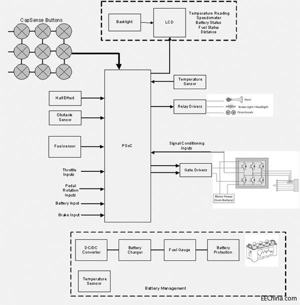
Figure 2: Block diagram of a PSoC-based electric bicycle solution
Implementation of electric bicycle system
In order to give a practical implementation of the electric bicycle system, this paper introduces a design based on Cypress PSoC 4. PSoC 4 devices are a perfect integration of microcontrollers with digital programmable logic, high performance analog-to-digital conversion, op amps with comparator modes, and standard communication and timing peripherals. The microcontroller is a 32-bit ARM Cortex M0 that operates at up to 48 MHz and offers up to 32 KB of flash and up to 4 KB of SRAM and 2 KB of internal EEPROM.
The implementation uses six P-channel MOSFETs and gate driver circuits on the board to drive a three-phase brushless motor. PSoC 4 devices have built-in PWM, clock, multiplexer and comparator for driving and controlling three-phase brushless motors. In addition, the built-in 16-bit PWM will be used to drive the FET gate driver circuit that controls the motor. The duty cycle of the PWM varies depending on the speed required by the user settings.
The PSoC4 features an internal op amp, PGA, comparator, and 12-bit 1MSPS SAR ADC that provides differential and single-ended modes, including sample-and-hold (S/H). The ADC can control motor speed by changing the PWM duty cycle and measure different sensor inputs to meet battery monitoring, low cost temperature sensing, obstacle sensing, and fuel sensing. This eliminates the need for any external amplifier, ADC or comparator.
Utilizing two current DACs (IDACs), the system features universal sensing and the ability to utilize capacitive sensing on any pin. The PSoC 4 architecture supports capacitive sensing components that support both manual and automatic tuning. The capacitive interface helps the entire electric bicycle system to achieve water resistance, while also directly driving the relay to fully meet the needs of speakers, brake lights, headlights, turn signals and LCD displays. The device operates from a voltage range of 1.71V to 5.5V and can be easily connected to other external peripherals for additional functionality. In addition, PSoC 4 supports two independent in-service reconfigurable serial communication modules (SCBs) with reconfigurable I2C, SPI or UART functions for internal and external peripheral communication.
Dc Gear Motor, namely Gear Reduction Motor, is based on ordinary Dc Motor , coupled with gear reduction gearbox.
The gear reducer is used to provide low speed and large torque.
At the same time, the gearbox with different deceleration ratio can provide different speed and torque.
Generally different industries, using different power dc motor, generally adopt custom parameter design pattern.
What are the four ratings of the Dc Gear Motor? The DC gear motor is often seen in our industrial production. Here Shunchang Motor gives you the knowledge of its four ratings. To talk about
1. Rated Current: The rated current is the maximum current allowed to flow through the armature winding of the DC deceleration motor in accordance with the specified operating mode, in A.
2. Rated Voltage: The rated voltage is the maximum additional voltage that the armature winding of the motor can work safely, unit V. It
3. Rated Speed: Rated speed refers to the rotational speed of the Gear Reducer Motor in the rated voltage, rated current and output rated power under the circumstances of operation, the unit is r/min. Such
4, rated power: rated power refers to the motor in accordance with the specified mode of operation can provide output power. For motor, rated power is the output of mechanical power on the shaft.

precision instruments and meters,automobile industry, medical equipment, consumer electronics, household appliances, electric glass doors and Windows,etc., wide application range

Features: gear motor drive precision, small volume, large torque, low noise, durability, low energy consumption, customized power design,easy installation, easy maintenance;Simplify design and save space.
Method of use: the best stable in horizontal plane, installed on the dc gear motor output shaft parts, cannot use a hammer to knock,knock prone to press into the dc gear motor drive, may cause damage to internal components, and cannot be used in the case of blocked.

Operating temperature range:
Geared motors should be used at a temperature of -10~60℃.
The figures stated in the catalog specifications are based on use at ordinary room temperature catalog specifications re based on use at ordinary room temperature (approximately20~25℃.
If a geared motor is used outside the prescribed temperature range,the grease on the gearhead area will become unable to function normally and the motor will become unable to start.Depending on the temperature conditions ,it may be possible to deal with them by changing the grease of the motor's parts.Please feel free to consult with us about this.
Storage temperature range:
Geared motors should be stored ta a temperature of -15~65℃.
In case of storage outside this range,the grease on the gearhead area will become unable to function normally and the motor will become unable to start.
Service life:
The longevity of geared motors is greatly affected by the load conditions , the mode of operation,the environment of use ,etc.Therefore,it is necessary to check the conditions under which the product will actually be used .The following conditions will have a negative effect on longevity.Please consult with us should any of them apply.â—Use with a load that exceeds the rated torque
â—Frequent starting
â—Momentary reversals of turning direction
â—Impact loads
â—Long-term continuous operation
â—Forced turning using the output shaft
â—Use in which the permitted overhang load or the permitted thrust load is exceeded
â—A pulse drive ,e.g.,a short break,counter electromotive force,PWM control
â—Use of a voltage that is nonstandard as regards the rated voltage
â—Use outside the prescribed temperature or relative-humidity range,or in a special environment.
â—Please consult with us about these or any other conditions of use that may apply,so that we can be sure that you select the most appropriate model.


when it come to volume production,we're a major player as well .each month,we rurn out 600000 units,all of which are compliant with the rohs directive.Have any questions or special needed, please contact us, we have the engineer group and best sales department to service to you Looking forward to your inquiry. Welcome to our factory.

Gear Motor
Gear Motor,Micro Gear Motor,Small Gear Motor,Bike Lock Gear Motor
Shenzhen Shunchang Motor Co., LTD. , https://www.scgearmotor.com