
I. Introduction
Since the introduction of the screw-type plastic injection molding machine in the 1950s, it has been more than 50 years old. Currently in the engineering plastics processing industry, 80% use injection molding. The plastic particles (ABS, polyethylene, modified polystyrene, etc.) are heated and eroded by multiple heaters in the barrel of the injection molding machine, injected into the mold cavity after supercharging with a screw, and the pressure is maintained after cooling to form a workpiece. The processing process. For plastics processing, the complete process of the injection molding machine is: mold clamping, injection molding, pressure maintenance, cooling, demoulding, and mold opening. The pressure maintaining and cooling, demolding and mold opening are carried out at the same time, that is, during the pressure holding process, the mold is cooled by the water; in the process of opening the mold, the ejecting thimble in the mold is gradually extended from the hidden place to make Note that the workpiece on the mold is peeled off and a machining process is completed after the mold is opened. Regardless of large, medium and small injection molding machines, the process flow is the same. At present, the vast majority of injection molding machines are hydraulically driven injection molding machines. The power required for the above process is provided by the oil pump in the hydraulic system. The pumps are divided into variable displacement pumps and quantitative pumps. During the operation of the injection molding machine, the load of each process during a work cycle varies greatly. The required flow and pressure of the hydraulic system are different. This change has been taken into account when producing the oil pump, and the flow and pressure required by the hydraulic system are changed. The oil supply of the oil pump is automatically increased or decreased to adapt. This oil pump is a variable pump and does not need to use a frequency converter for speed control. Another widely used oil pump is a metering pump. Its fuel supply is constant. The flow rate and pressure during the operation of the injection molding machine are adjusted by the flow proportional valve and the pressure valve. The excess amount of oil passes through the relief valve. Return to the tank. In this way, the wear of the valve and the oil pump is exacerbated, causing the oil temperature to rise and the motor noise to be excessive. In addition, from the design of the injection molding machine, usually in the design of the oil pump should have a margin, generally consider 10% to 15%, but the series of oil pump is limited, often choose the right type of oil pump when the model up There is a serious "big horse-drawn car" phenomenon, resulting in a lot of energy wasted. Therefore, it is of great significance to carry out frequency conversion speed adjustment for the injection molding machine of the quantitative pump to save electric energy and improve economic efficiency.
Second, energy-saving injection molding machine analysis
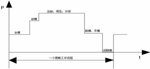
Figure 1 Relationship between system oil pressure and time
According to the process of the injection molding machine, the relationship between the system oil pressure P and the time t is plotted in Fig. 1. It can be seen from the figure that the mold clamping and stripping, the mold opening system requires lower oil pressure, and the time is shorter; and injection , Pressure maintenance, cooling system requires high oil pressure, and a long time, generally 40% to 60% of a working cycle, the length of time and the processing of the workpiece; shorter interval, which is also the case with the processing of the workpiece Regarding, sometimes it may not be an interval. The above figure is only a simple approximation. In fact, if the injected screw is driven by an oil motor, the system oil pressure at the time of injection will be higher. The weight of the workpieces processed by injection molding machines ranged from tens of grams to tens of thousands of grams, and the largest injection molding machine has reached 92,000 grams. Therefore, the injection molding machine has medium, small and large points, and the time for processing one gram of small workpieces and processing large workpieces of several kilograms is also not the same; that is, the raw materials for the same injection molding machine and processing workpiece are different. The pressure and time required in each process section also vary. The setting of these process parameters is determined by the field technicians based on empirical data and test conditions.
From Figure 1, we can see that in a cyclical work flow, the change in load causes a relatively large change in system pressure, but the oil pump is still running at 50Hz, and its fuel supply is constant, and excess hydraulic oil flows back to the fuel tank through the relief valve. Do nothing and waste electricity in vain. The frequency conversion of the oil pump is regulated, and the quantitative pump is changed to the characteristics of the variable pump. When the pressure required by the system is high, the oil pump motor runs at 50Hz. When the required pressure is low, the frequency converter runs at a reduced frequency. The shaft output power of the motor is proportional to the product of the outlet pressure and flow rate of the oil pump. After the rotation speed of the oil pump motor is reduced, the power of the output shaft is reduced, and an effective energy saving can be achieved. Generally, the energy saving rate is 20% to 50%.
Third, the injection molding machine frequency conversion energy-saving speed control transformation program
Hydraulic injection molding machines have vertical and horizontal types. Dozens of grams of vertical injection molding machine, oil pump uses a gear pump, the motor capacity is also smaller, electrical control circuit is also relatively simple. During the retrofit, the inverter is connected to the power supply circuit of the motor, and then the signal (0~1A) of the flow proportional valve is converted into a 4~20mA signal and sent to the corresponding port of the inverter, so that the process changes The flow of hydraulic oil is also changing. Generally speaking, it is better to take the flow signal with a relatively large change of relative value as the control signal, and the change of the control signal has a larger range of frequency adjustment of the frequency converter; and the relative value of the pressure signal changes less, and the frequency adjustment range of the frequency converter is smaller. . If the inverter frequency adjustment range does not meet the process requirements, you can use the frequency converter's function "frequency gain" to adjust. Injection molding machine inverter is based on the general inverter has added 0 ~ 1A signal conversion link, more convenient to use.
More than 60 grams are horizontal injection molding machines, 60-500 grams of injection molding machines, some are oil pumps, and some are two oil pumps. The transformation of an oil pump injection molding machine is the same as that of a vertical injection molding machine. The signal of 0~1A is still taken from the flow proportional valve as the speed adjustment signal of the inverter. Although the speed adjustment signal is fed back to the inverter by the hydraulic circuit element, there is no given signal in the control loop, so the control still belongs to the open loop control. the way. It is also because of energy-saving reasons that large and medium injection molding machines may have more than one oil pump. For example, Mitsubishi 850-MM, 1300-MM, 1800-MM, 2000-MM injection molding machines all have three oil pumps. Corresponding to the injection molding process, the required system pressure is low during the mold closing phase. Only the #1 oil pump works. When the system pressure required for the mold clamping phase is high, the #2 oil pump is put into operation again. The highest pressure is required. Three oil pumps are put into operation at the same time. The pressure required for demoulding and opening molds is low, and then the 3# and 2# oil pumps are stopped respectively. As long as the boot, 1 # pump has been running. Using three small oil pumps to work intermittently at different stages of the process requires energy savings compared to using a large pump. How to transform an injection molding machine with two or more oil pumps? Here is an example of the modification of the Mitsubishi 1800-MM injection molding machine. Mitsubishi 1800-MM injection molding machine has three 45KW oil pump motors. One inverter drives 1# oil pump motor. The adjustment signal of the frequency converter is taken from the injection molding machine flow proportional valve. In this way, the frequency of this frequency converter is related to the hydraulic oil of the injection molding machine. The flow changes and changes. The other two pump motors can be driven by two inverters. However, these two inverters do not perform speed control on the motor and only perform two-phase control, ie start and stop. Control start and stop signals of the frequency converter are taken from the start and stop signals of the original oil pump motor. The upper limit frequency of the inverter is set below 50Hz. The specific setting value is related to the workpiece size, material, barrel temperature and other factors. If the frequency converter operates below 50Hz, it can save energy. In fact, there are margins in the design of the injection molding machine, and the oil pressure required to change the size of the workpiece and the material changes. If the injection pressure is too large and the clamping force is insufficient, the workpiece will be flashed; if the injection force is insufficient, the plastic in the mold cavity will be less than full, the workpiece will be scrapped; when the pressure is insufficient, the plastic in the workpiece will shrink when the plastic is thick .
Fourth, pay attention 1. Selection of frequency converter
The loading nature of the injection molding machine is constant torque, the mechanical characteristics are hard, and the dynamic characteristics are relatively high. Therefore, the inverter for injection molding machine should be used. Injection molding machine dedicated frequency converter is based on the general frequency changer has added 0 ~ 1A signal conversion link, improve the use of performance. Considering that there are certain requirements for the injection molding process at each stage, the acceleration and deceleration time of the inverter should be short, generally 1 second, so the capacity of the inverter must be appropriately increased.
2. Standby system
When the injection molding machine is used for frequency conversion energy-saving transformation, the original frequency-frequency starting circuit is reserved for backup, so once the frequency converter has a fault, the industrial frequency starting oil pump motor can continue to operate.
3. Frequency converter signal extraction point
Take the flow signal of the double proportional valve (0~1A) and convert it into 4~20m signal to the corresponding port of the inverter. The flow signal takes a relatively large value as a control signal to expand the adjustment range. The relative change of the pressure signal is small, and the adjustment range of the inverter frequency is smaller. If the adjustment range of the inverter can not meet the needs of the forming process, you can use the frequency gain function of the inverter to adjust.
4. Pre-commissioning precautions
Injection molding machine frequency conversion energy-saving electrical transformation is relatively simple, but before the transformation should be a detailed understanding of the injection molding machine working conditions, familiar with the injection molding machine process, debugging should pay attention to the following matters: Check the original injection molding machine before installation circuit wiring, including the main circuit And control circuit; carefully observe the injection molding machine frequency operation is normal, the pump motor is often in an overload state; according to the injection molding machine mold and injection molding process to observe the potential of injection molding machine power saving transformation; control signal line attention to the positive and negative polarity Do not reverse Separate the signal line from the main circuit line.
5. Inverter interference with digital instrumentation of injection molding machine
Now widely used on injection molding machines is AC-DC-AC frequency converters, whose output current contains harmonic components, which may cause interference to the injection molding machine. The most susceptible to interference is the temperature control instrument. Therefore, the installation of the frequency converter should be done well. Anti-jamming measures. Inverter shall be equipped with input and output reactors or high-frequency magnetic rings, etc.; control lines introduced into the inverter shall be shielded; the chassis shall be reliably grounded; do not make the input and output cables of the inverter parallel to the control signal lines of the inverter. Or bundled together; when the inverter is installed inside the injection molding machine, pay special attention to ventilation and heat dissipation.
V. Debugging Common Problems and Processing Methods
Due to the particularity of the injection molding machine process, various failures will be encountered during the transformation. The following are the problems encountered in the frequency conversion of the injection molding machine and the treatment methods.
1. No change in inverter frequency
Because the inverter adopts the valve-controlled current signal of the injection molding machine to adjust the speed, the frequency of the inverter is displayed as 0.0 (some inverters show 0). The main reason is that the signal polarity is reversed; the signal is wrong; the signal wiring The port is inconsistent with the parameter setting; the auxiliary power supply failure of the injection molding machine, etc. This type of failure should be checked first. The category of valve control of the injection molding machine is the current signal, voltage signal or pulse control signal (some models), and the positive and negative polarity of the signal. Does it correspond to the inverter control terminal?
2. Noisy oil pump
After the inverter runs, some injection molding machines will emit abnormal noise. At this time, the source of the noise should be judged whether it is from the motor or the oil pump. If the noise of the pump is due to: the injection molding machine has too little hydraulic oil, there is air suction; Machine oil filter or oil circuit blockage; injection pump oil pump blade wear is more serious; encountered should first check the injection pump oil pump, troubleshooting before running, and when the injection is in low speed and high pressure working conditions, there will be abnormal oil pump noise In this case, it is appropriate to increase the speed signal.
V. Conclusion
The frequency conversion speed control of the injection molding machine is mainly aimed at energy saving. Small, medium to large injection molding machines can be retrofitted with frequency converters for energy saving. At the beginning of the transformation, it involved the estimation of energy efficiency. The energy saving of injection molding machines is mainly related to the injection molding process and it is difficult to make an accurate calculation. In general, after transformation, an injection molding machine of an oil pump motor saves energy between 20% and 50%, and the injection molding machines for multiple oil pump motors Energy saving is between 15% and 30%. In addition, the reduction of the speed of the oil pump reduces the wear of the machinery, and the indirect economic benefits cannot be overlooked.