First, the working principle and technical specifications of the frequency converter
1ã€Inverter principle introduction
The frequency converter is a power control device that utilizes the on-off function of the power semiconductor device to convert the power frequency power source to another frequency. Low-voltage inverters mainly adopt the AC-DC-AC method, which first converts the AC power supply of the industrial frequency to a DC power supply through a rectifier, and then converts the DC power supply into an AC power supply whose frequency and voltage can be controlled to supply the motor. The inverter's circuit is generally composed of four parts: rectification, intermediate DC link, inverter and control. The rectifying part is a three-phase bridge type uncontrollable rectifier, and the inverter part is an IGBT three-phase bridge type inverter, and the output is a PWM waveform. The intermediate DC link is a filter, a DC storage energy and a buffer reactive power. The speed of the motor can be freely adjusted via the frequency converter.
Figure 1 shows the block diagram of the control circuit in the inverter.
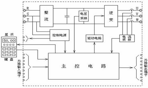
Fig. 1 The block diagram of the control circuit in the inverter
2nd, frequency changer technical specification
control
Control Method
Space voltage vector control
Frequency setting resolution
Numbers: 0.01 Hz (below 100 Hz), 0.1 Hz (above 100 Hz)
Simulation: 0.05 Hz / 50 Hz, Output frequency range: 0 – 300 Hz
Frequency accuracy
Number: 0.01% of maximum output frequency
Simulation: 0.1% of the maximum output frequency
V/F ratio
Linear, square root, arbitrary V/F
Overload capacity
Rated current 150 % -1 minutes, rated current 200% - 0.5 seconds. (The characteristic is inversely proportional to time)
Torque compensation
Manual torque compensation (0 - 20 %), automatic torque compensation
run
input signal
Operation mode
Keyboard/terminal/RS485 communication
Frequency setting
Analog: 0 - 10V / 4 - 20 mA/, additional port for daughter board (0 - 10V/4 - 20 mA)
Number: Keyboard/RS485 Communication
Start signal
Forward Reverse
Multi-speed
Up to 8 speeds can be set (using multi-function terminals)
Acceleration time
0-6000 seconds, acceleration and deceleration time can be switched
Acceleration and deceleration mode: linear, S type
emergency stop
Interrupt the output of the frequency converter
Inching
Slow running
automatic running
Automatic operation through the set parameters (7-step speed)
Fault reset
When the protection function is in the valid state, the fault state can be automatically reset.
output signal
Operating status
Frequency detection level, overload alarm, over voltage, under voltage, inverter overheat, running, stop, constant speed, automatic program operation
Fault output
Contact output - AC 250V 1A, DC 30V 1A
Analog output
Choose from output frequency, output current, output voltage, DC voltage
(Output voltage: 0 - 10V)
Operation function
DC braking, frequency limitation, frequency hopping, slip compensation, reverse protection, PID control, etc.
Protective function
Inverter protection
Over voltage, under voltage, over current, broken fuse, ground fault, frequency inverter overheat, motor overheat, phase loss, overload protection, external fault 1,2, communication error, lost speed command, hardware fault, option error, etc.
Inverter alarm
Stall protection, overload alarm, temperature sensor failure.
Instantly power off
Less than 15 milliseconds: continuous operation
Greater than 15 milliseconds: Allow automatic restart
display
keyboard
Running information
Output frequency, output current, output voltage, set frequency, operating speed, DC voltage
Error message
When the fault protection operation status, there are 3 fault history information saved.
surroundings
Ambient temperature
-10 °C to 40 °C
Storage temperature
-20 °C to 65 °C
environment humidity
Maximum 90 % RH. (non-condensing)
Height/vibration
Below 1,000 m, below 5.9m/s2 (=0.6g)
Application location
No corrosive gas, flammable gas, oil mist or dust and others
cooling method
Forced air cooling
Second, energy-saving analysis
The basic principle of frequency conversion speed regulation technology is based on the relationship between the motor speed and the input frequency of the working power supply: n = 60 f(1-s)/p, (where n, f, s, and p represent the speed, input frequency, Motor slip ratio, number of poles of the motor pole; the purpose of changing the motor speed by changing the frequency of the motor power supply. According to the basic laws of fluid mechanics, it can be known that fans and pumps are all square torque loads. The rotational speed n, flow Q, pressure H, and shaft power P have the following relationships: Qâˆn, Hâˆn2, Pâˆn3; The flow is proportional to the speed, and the pressure is proportional to the square of the speed. The shaft power is proportional to the cube of the speed. The following figure shows the pressure H-flow Q curve characteristic diagram: Fan and pump When the pipeline characteristic curve R1 is working, the working point is A, and the flow pressure is Q1, H1 respectively. At this time, the fan and pump are required. The power is proportional to the product of H1 and Q1, which is proportional to the area of ​​AH1OQ1. Since the process requires reducing the flow to Q2, in fact, by increasing the resistance of the pipe network, the operating points of the fans and pumps are moved to point B on R2, and the pressure is increased to H2. At this time, the power required by the fans and pumps is increased. Proportional to the product of H2 and Q2, which is proportional to the area of ​​BH2OQ2. Obviously, the power required by fans and pumps has increased. Although this kind of adjustment mode control is simple, but the power consumption is large, it is not conducive to energy saving, and a simple control method is used in exchange for a high running cost.
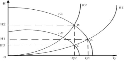
N1- represents the characteristics of the motor running at rated speed;
N2- represents the characteristics of the motor running at a reduced speed at n2 speed;
R1- represents the resistance characteristics of fans and pumps with minimum resistance;
R2- represents the resistance characteristics of fans and pumps when the resistance of the pipeline increases to an array.
If frequency control is used, the fan speed is decreased from n1 to n2. At this time, the operating point moves from point A to point C, the flow rate is still Q2, and the pressure is reduced from H1 to H3. In this case, the power required by the fan after frequency conversion is proportional to the power. The product of H3 and Q2, which is proportional to the area of ​​CH3OQ2, shows that the decrease in power is evident from the graph. For fan and pump equipment with energy-saving effect of frequency control, usually using the following two ways to calculate: If the use of frequency control, fan speed from n1 down to n2, then the work point from point A to point C, The flow rate is still Q2, and the pressure is reduced from H1 to H3. At this time, the power required by the fan after frequency conversion is proportional to the product of H3 and Q2, that is, proportional to the area of ​​CH3OQ2. From the figure, the reduction in power is obvious.
Third, the pre-reformation equipment conditions
Your company's equipment is to meet the different water flow through adjusting the valve opening angle of the mechanical adjustment method, this operating mode has the following shortcomings: (1) motor and fan speed is high, the load intensity is heavy, serious waste of energy; (2) The electrical control is directly started, and the current has large impact on the power grid at startup, the required power (grid) capacity is large, and the power factor is low; (3) The mechanical shock at startup is large and the service life of the equipment is low; (4) The electrical protection characteristics are poor. In the event of a mechanical failure of the load, it cannot be instantaneously actuated to protect the equipment. The use of frequency converters can achieve large soft stops and soft rises of motors, avoiding voltage surges at startup, reducing motor failure rates, and extending service life, while also reducing capacity requirements and reactive power losses on the grid.
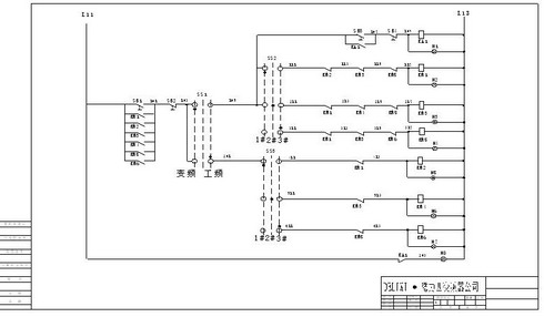
Fourth, frequency conversion reform program
The cold water pump system of your company's second workshop is one use and one preparation, the frequency conversion control cabinet has the switching function, you can choose 1# or 2# to start, and you can select 1# frequency start when the inverter fails to ensure the continuity of the production. . Frequency conversion automatically adjusts the motor speed according to the pressure signal.
Device name
model
Quantity
Note
Inverter
CDI9000-G220T4
1
breaker
CDM1-630A
1
Contactor
CJ20-630A
3
Transfer switch
LW5-16D/2
2
Buttons
LAY7 GN
2
LED
LD11-22 380V
5
Ammeter
42L6-500/5
1
Voltmeter
42L6-450V
1
Transformer
BH0.66-/5
1
Cabinet
1600*600*500
1
annex
Wire rod, material, copper row
1